
Microcontact printing

a micro-contact printing and printing technology, applied in the field of micro-contact printing, can solve the problems of inability or difficulty for users to consistently adjust the rate at which the air pressure drops within the variable-pressure chamber, and the above-described conventional micro-contact printing practices, etc., to achieve the effect of generating undesired patterning results

Inactive Publication Date: 2006-10-10
MASSACHUSETTS INST OF TECH
View PDF13 Cites 62 Cited by
  • Summary
  • Abstract
  • Description
  • Claims
  • Application Information

AI Technical Summary

Benefits of technology

The patent describes a system for printing patterns on a surface using a microcontact printing approach. The system includes an actuator and a control system to precisely control the force or pressure exerted between the stamp and the print surface. This allows for the transfer of a print medium such as a thin layer of material onto the surface in a reproducible manner. The system can also have a third actuator to selectively displace regions of the stamp to provide a contact region between the stamp and the surface and to selectively control expansion or propagation of the contact region. The system can also include sensors to measure position and applied force, and both open and closed loop control can be used. Overall, the system provides a more consistent and accurate way to print patterns.

Problems solved by technology

Unfortunately, there are deficiencies to the above-described conventional microcontact printing practices.
In particular, much of the above-described conventional microcontact printing practices are carried out by hand with little mechanization resulting in a lack of accuracy and consistency in microcontact printing results.
For example, in connection with the above-described conventional microcontact printing apparatus which requires a user to (i) manually operate a vacuum source that connects to a variable-pressure chamber and to a platform, and (ii) manually operate an air-actuated piston to move the substrate into contact with the microcontact printing stamp, there are abundant opportunities for operating inconsistencies which would result in different microcontact printing effects from one microcontact printing operation to another.
In particular, since the air-pressure within the variable-pressure chamber is under manual control (e.g., the user manually opens and / or adjusts valves to a vacuum pump), it is difficult or impossible for the user to consistently adjust the rate at which the air pressure drops within the variable-pressure chamber.
Thus, there is little or no control over how much ink solution (i.e., solvent) evaporates from the microcontact printing stamp before the stamp contacts each substrate from one microcontact printing operation to another.
Additionally, since the substrates reside within the variable-pressure chamber during the microcontact printing operation, it is difficult and laborious to change substrates after completing the microcontact printing operation.
Furthermore, since the user visually aligns the microcontact printing stamp with the surfaces of the substrates, there is no guarantee that the stamp is actually substantially parallel with the surfaces of the substrates thus permitting inconsistent microcontact printing stamp operations to occur.
Moreover, after the platform assembly of upper and lower members having predefined spring tension and shock absorption characteristics, plungers, and compression stops have been configured, there is little or no control over the amount of force between the microcontact printing stamp and the substrate.
As a result, the amount of force between the stamp and each substrate could drift (e.g., decrease or increase) over a period of time and use, thus producing patterns with too much ink, too little ink, smudged patterns, incomplete patterns, etc.
Similarly, in connection with the above-described conventional microcontact printing approach which involves a user manually operating a set of pressure valves to provide air pressure differences between top and bottom surfaces of a flexible microcontact printing stamp in order to bend the stamp, there is a strong likelihood of inconsistencies between microcontact printing operations between substrates.
In particular, since the user manually controls the air pressure valves, it is difficult or impossible for the user to consistently control the amount of time of each microcontact printing operation and thus difficult or impossible for the user to control the amount of ink solution that evaporates from the microcontact printing stamp before the stamp contacts each substrate from one microcontact printing operation to another.
Also, it is difficult to indirectly control the exact position and shape of the flexible microcontact printing stamp by manually adjusting the air pressure on each side of the stamp thus allowing for contact position and stamp shape inconsistencies.
Furthermore, in connection with the above-described conventional microcontact printing approach which involves a user manually rolling a cylindrical-tool over a substrate as in a rotary press, it is difficult for the user to provide consistent force control, i.e., it is difficult for the user to consistently control the amount of force between the stamp and the substrate since rolling at a fast rate or with more pressure will provide different results than rolling at a slow rate or with less pressure.
Moreover, the stamps remain in distorted states once attached to the rollers, and it is difficult to control distortions of the elastomeric material of the microcontact stamps when bowing or bending the stamps in an extreme manner to form the cylindrical-tool, thus providing further opportunity to generate undesired patterning results.

Method used


Image

  • Microcontact printing
  • Microcontact printing
  • Microcontact printing

Examples


Embodiment Construction

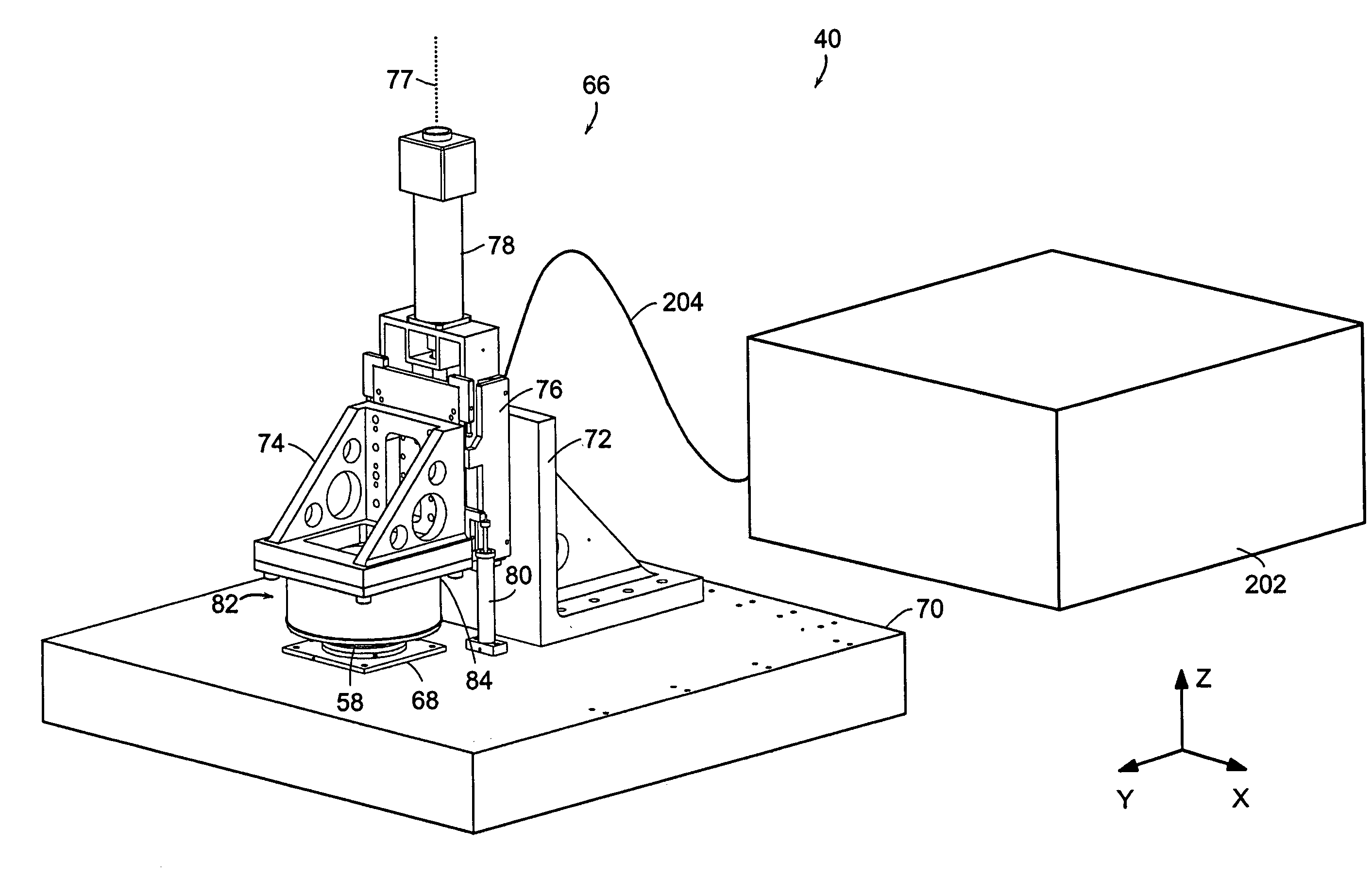
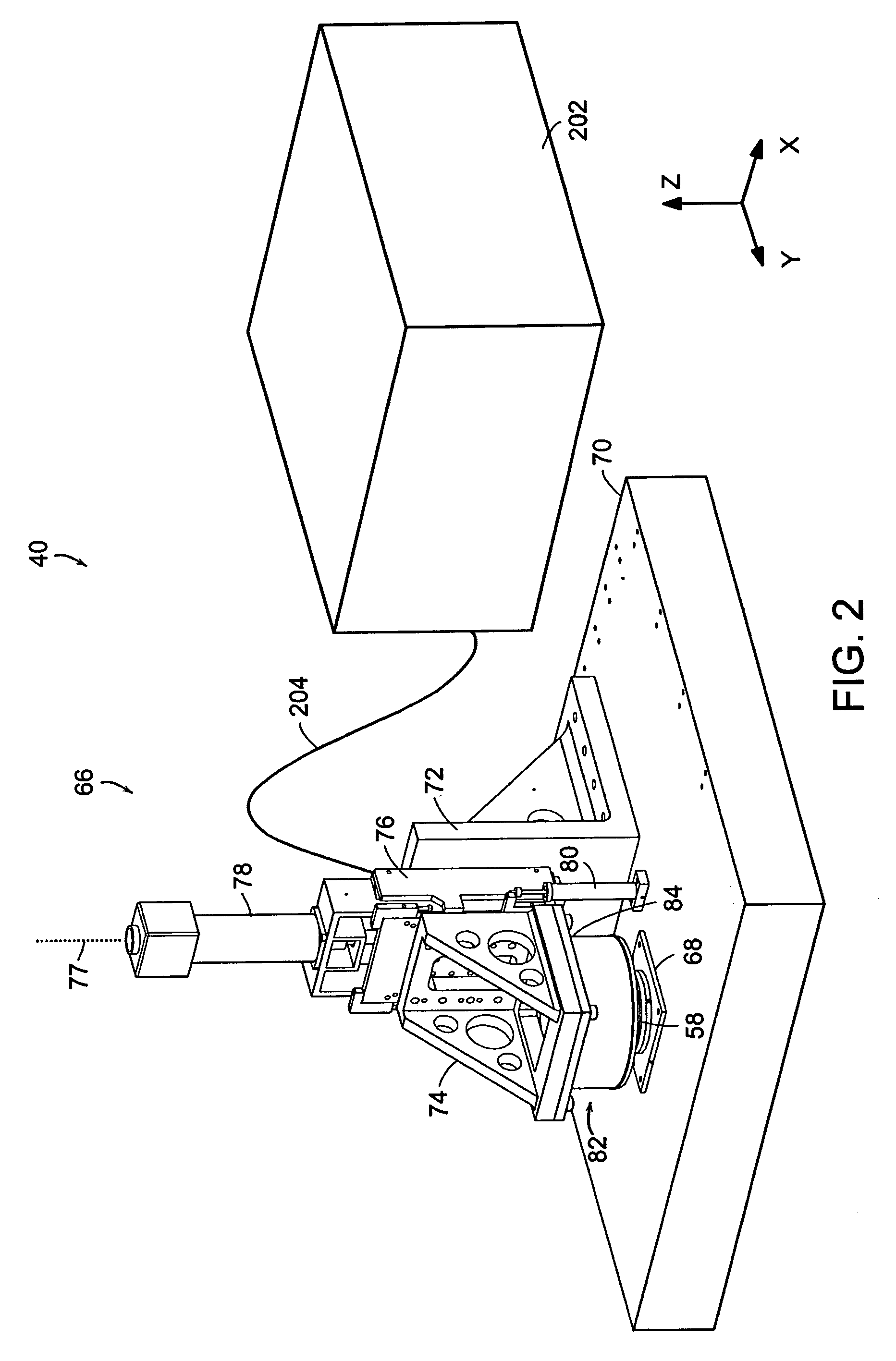
[0082]Referring to the drawings in detail, where like numerals indicate like elements, there is illustrated a microcontact printing tool in accordance with the present invention designated generally as 40.

[0083]Microfabrication has long been used for semiconductor applications. Recent developments in biology and chemistry are now employing microfabrication as well. While some of the procedures and techniques from the semiconductor industry can be carried over for use in these new applications, biologists and chemists often have specific requirements that cannot be met by conventional means.

[0084]Microcontact printing is a method of microfabrication that can satisfy many of these demands. As one of the suite of soft lithographic fabrication techniques, microcontact printing permits the patterning of microfeatures that can be tailored to have additional functionality for chemical or biological activity. This technology has the capability of overcoming several of the drawbacks of photo...


PUM

PropertyMeasurementUnit
sizeaaaaaaaaaa
sizeaaaaaaaaaa
areaaaaaaaaaaa

Abstract

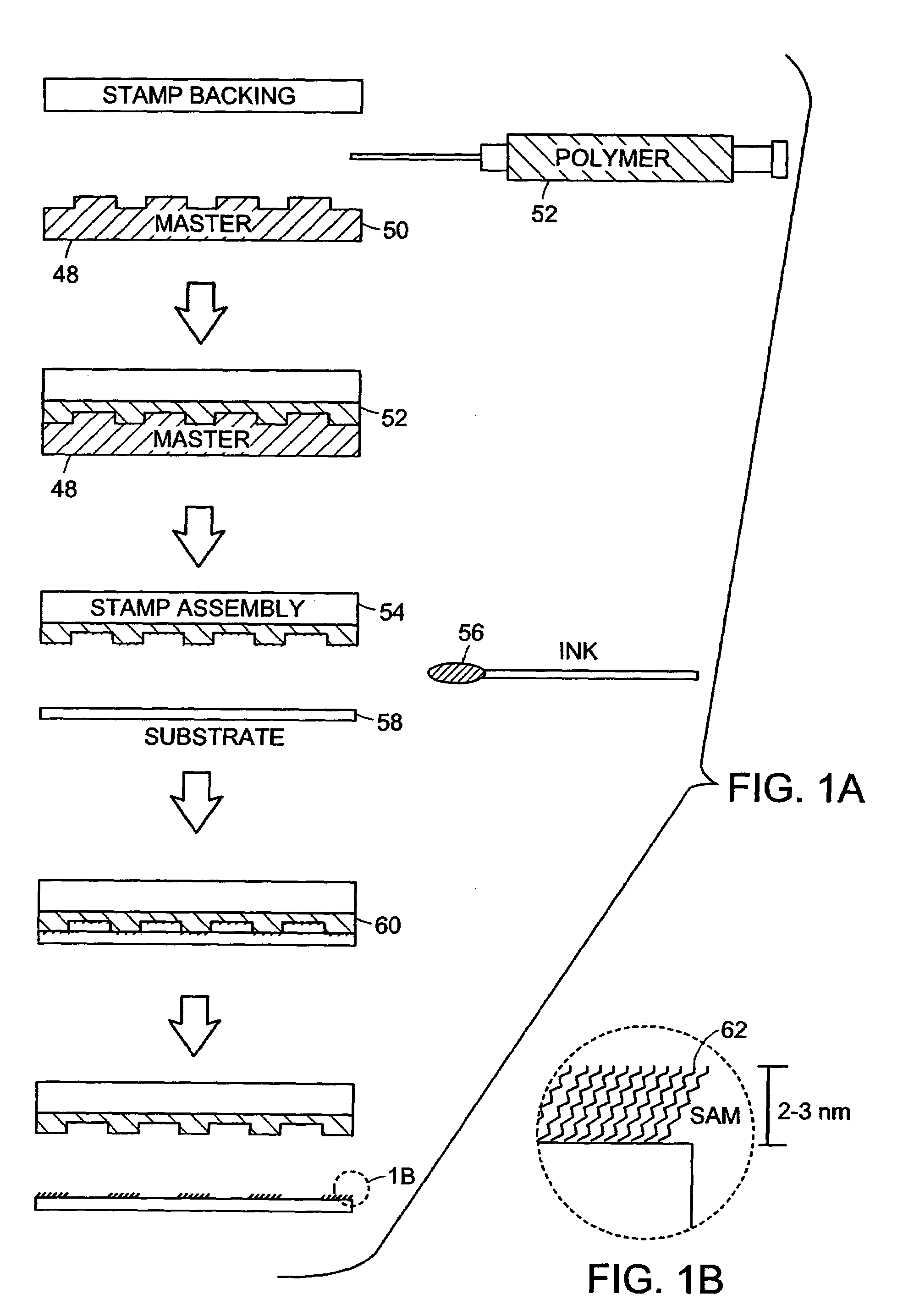
A microcontact printing tool having a print unit including a stamp head with a stamp and a wafer chuck for retaining a substrate. The stamp contained by the stamped head movable relative to the substrate by an actuator and a stage. A plurality of sensors detect the position of the stamp relative to substrate. A method of using the printing tool that includes a real-time feedback for consistent and accurate application of force during the printing of the substrate. The stamp head includes a pressure chamber carrying the stamp. The stamp backing is deflected prior to contact of the stamp with the substrate to form a minimum point and the stamp backing and the stamp is returned to a plane to create a printing propagation contact. An apparatus and method of producing the stamp on a stamp backing. The apparatus has a master backing and a stamping backing in close proximity and the stamp material drawn in through a vacuum. The stamp is separated from the master by use of a parting fluid.

Description

CROSS REFERENCES TO RELATED APPLICATIONS[0001]This application claims the benefit of priority to U.S. Provisional Application No. 60 / 347,225, filed Jan. 11, 2002 and entitled “Microcontact Printing Apparatus and Method.” The entire contents of the above application are incorporated herein by reference.BACKGROUND OF INVENTION[0002]In general, microcontact printing is a “soft lithography” process which involves the application of coating in the form of small structures (e.g., submicron patterns) to substrates. Such structures are useful in a variety of fields including chemistry, biology, and semiconductor and integrated circuit processing. For example, in the fields of chemistry and biology, microcontact printing is useful in forming micropatterns for drug and cellular measurement.[0003]There are a variety of approaches to microcontact printing. In one conventional approach, a conventional microcontact printing apparatus includes a support structure for holding a microcontact printin...

Claims


Application Information

Patent Timeline
Patent Type & Authority Patents(United States)
IPC IPC(8): B41K1/38B29C33/10B41F17/00B41M1/02G03F7/00G03F9/00H01L21/00H01L21/68
CPCB29C33/10B82Y10/00B82Y30/00B82Y40/00G03F7/0002H01L21/67282B41M1/02G03F9/00H01L21/68Y10S425/808Y10S425/06
Inventor KENDALE, AMAR MARUTITRUMPER, DAVID L.
Owner MASSACHUSETTS INST OF TECH
Learn More