Multi-stage modular rotary internal combustion engine

a rotary internal combustion engine and multi-stage technology, applied in the direction of liquid fuel engines, machines/engines, rotary piston liquid engines, etc., can solve problems such as rotor torque, and achieve the effect of reducing exhaust pollution and adding power

Active Publication Date: 2006-10-10
HORSTIN ABRAHAM H
View PDF11 Cites 39 Cited by
  • Summary
  • Abstract
  • Description
  • Claims
  • Application Information

AI Technical Summary

Benefits of technology

[0015]It is the primary objective of this invention to provide a Multi-Stage Modular Rotary Internal Combustion Engine of the Vane type, that is simple in construction, robust in design, easy to manufacture, reliable in operation, has a high power output, compact size and is clean burning with reduced harmful emissions. Another object of the present invention is to provide water cooling of the Housing Modules and oil cooling and lubrication of moving parts. The objects of this invention are realized by the following the technical solutions. According to the invention a Multi-Stage Rotary Internal Combustion Engine with permanently guided Vanes is presented. It consists of a Compressor Unit providing scavenge and super charged air, a Combustor Unit that incorporates a compressing portion, a working ignition and expansion portion, an Afterburner Unit comprising an expansion and exhaust portion, an ignition system, and a cooling system.

Problems solved by technology

The power output is realized by the expanding gas in the Combustor acting on the extended Vanes that slide around the periphery of the Housing's bore, resulting in Rotor torque.

Method used


Image

  • Multi-stage modular rotary internal combustion engine
  • Multi-stage modular rotary internal combustion engine
  • Multi-stage modular rotary internal combustion engine

Examples


Embodiment Construction

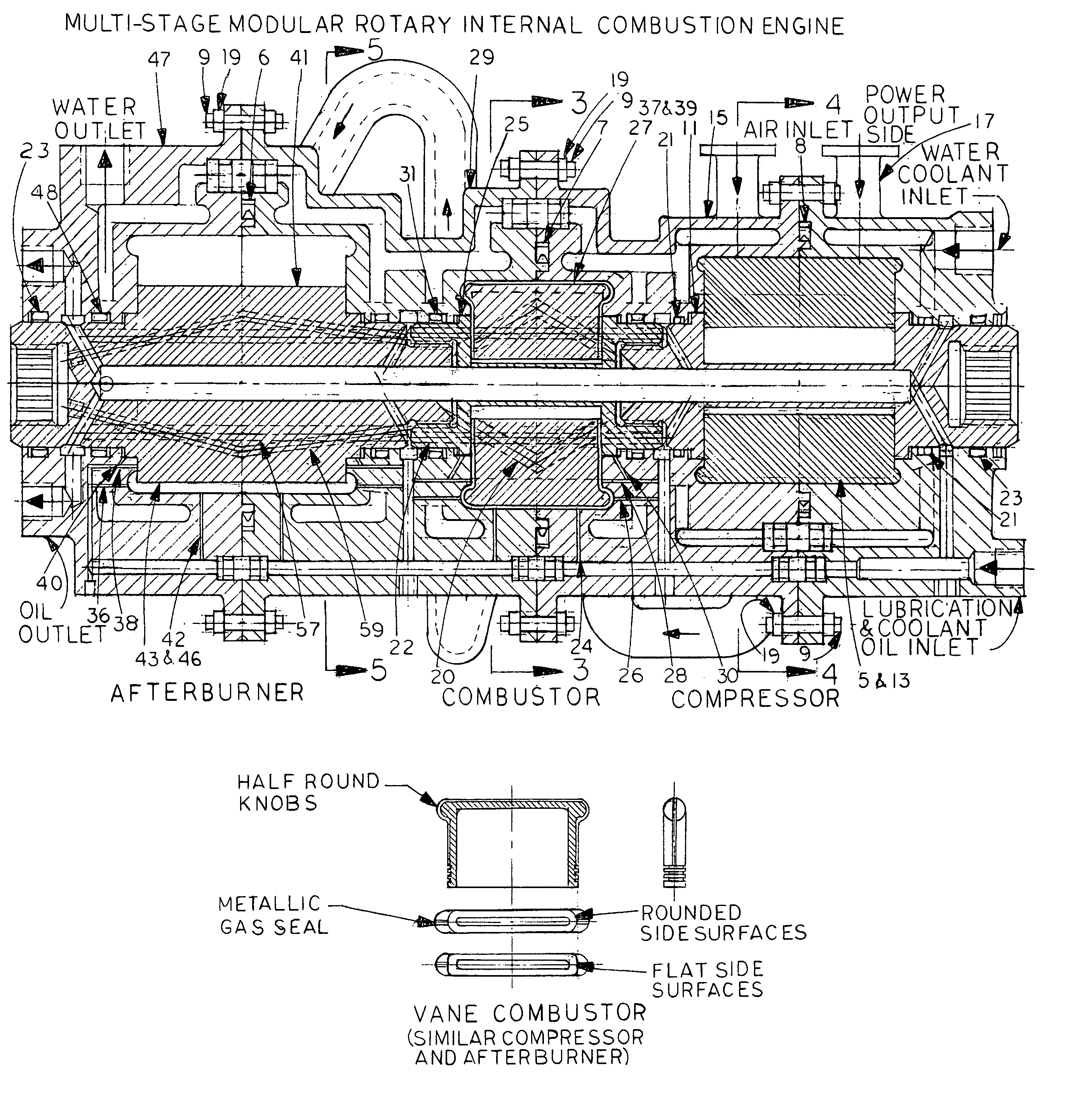
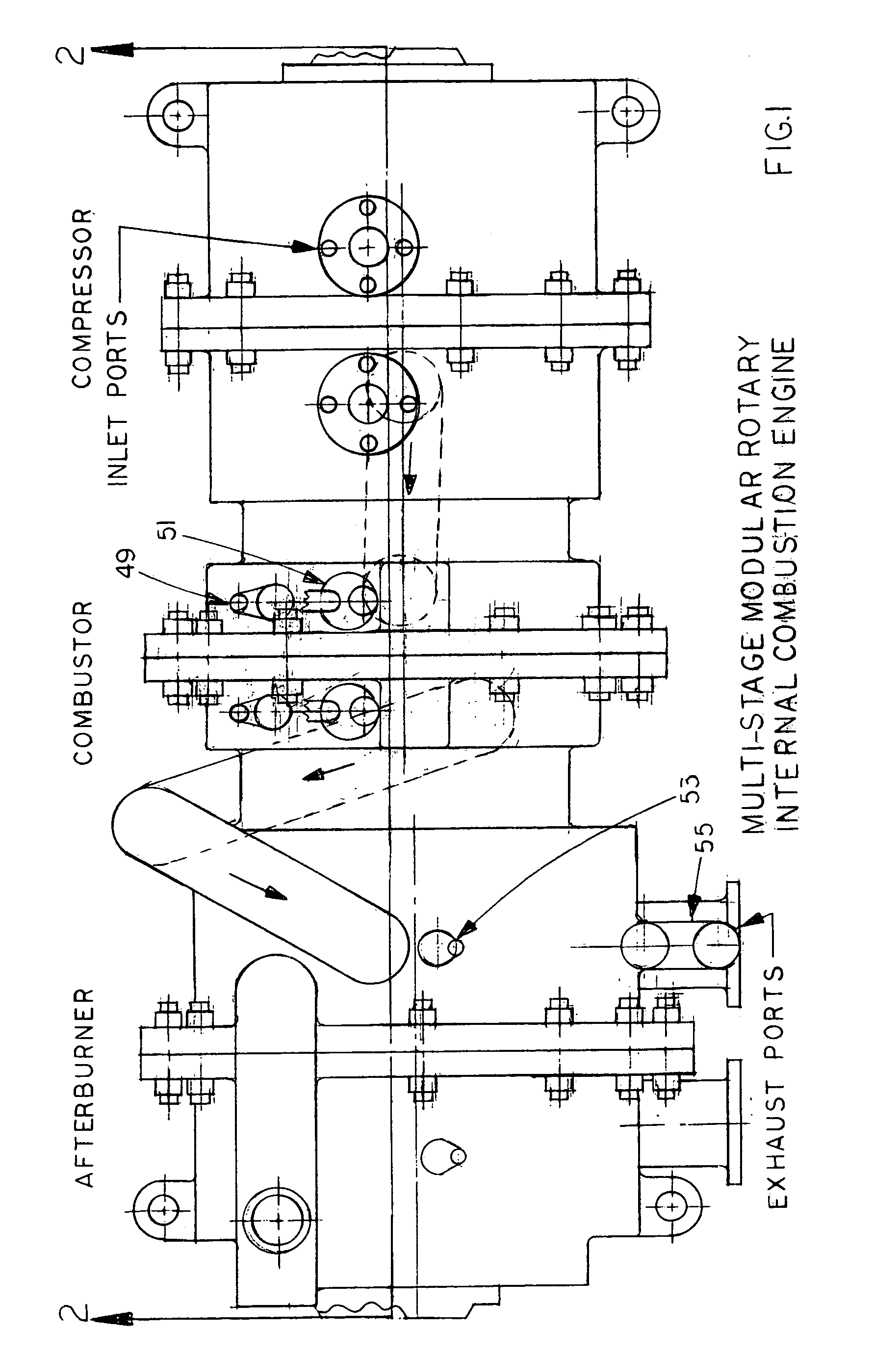
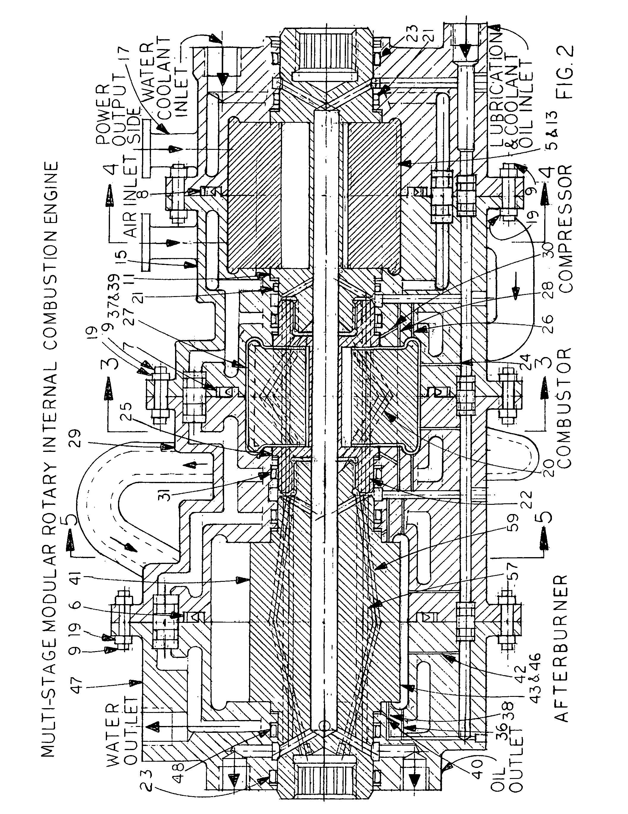
[0047]The Multi-Stage Modular Rotary Internal Combustion Engine as exhibited in FIG. 1 and FIG. 2 comprises a Compressor Unit, a Combustor Unit and an Afterburner Unit combined and secured by means of bolts and nuts to form one assembled module. Several modules could be combined in series or in a parallel configuration.

[0048]For the sake of illustrating the invention clearly, external apparatus such as fuel injection and ignition system, water cooling radiator and pump, oil lubrication pump system, starting system and external piping are all omitted.

[0049]The primary objective of this invention is to illustrate the operation of the embodiment of this Multi-Stage Modular Rotary Internal Combustion Vane Engine system, which is different from patented rotary engine systems.

[0050]With reference to FIG. 2, FIG. 4 and FIG. 4A: The Compressor Unit comprises a hollow core shaft with splines on opposite ends. A cylindrical Rotor 11, provided with radial blind slots, in which slidable and mov...


PUM


Abstract

A three-stage internal combustion rotary engine, comprised of: a compressor feeding compressed air to a combustor for compression, fuel injection, combustion, and expansion of gases which rotate the rotor. The combustor rotor generates torque and drives the compressor and afterburner rotors simultaneously. The afterburner receives the combusted gases and scavenged air from the combustor for secondary combustion and expels the exhaust gases. Each unit consists of a housing joined together on a common axis and a rotor with a shaft mounted in an eccentric position of the housing side-walls. The shafts are interconnected by splines. The rotors have radial blind slots which contain slidable, movable vanes fitted with half-round knobs on opposite sides, aligned with the top surface and fit in the hemispherical grooves on the interior side-walls of the housing. This maintains a permanent contact with the interior housing periphery, regardless of gas pressures and rotating speed.

Description

CROSS-REFERENCE TO RELATED APPLICATIONS[0001]Not ApplicableFEDERALLY SPONSORED RESEARCH[0002]Not ApplicableSEQUENCE LISTING OR PROGRAM[0003]Not ApplicableBACKGROUND OF THE INVENTION–FIELD OF INVENTION[0004]This invention relates to a Three-Stage Rotary Internal Combustion Engine of the Vane type, which includes a Compressor Unit, Combustor Unit and Afterburner Unit.INTRODUCTION[0005]A three-Stage Rotary Internal Combustion Engine used as a prime mover, is disclosed to have a Compressor Unit to feed compressed air to a Combustor Unit for further compression. The Combustor has a means of fuel injection and ignition at a high degree of compression. The Combustor's Rotor is driven by expansion of the combusted gases. An Aterburner Unit receives the combusted gases and scavenge air from the Combustor Unit for reburning, additional work and exhaust. Each Unit consists of a cylindrical Rotor that has a shaft on both ends. The Combustor Unit shaft is connected by means of splines on one end...

Claims


Application Information

Patent Timeline
Patent Type & Authority Patents(United States)
IPC IPC(8): F02B53/00F01C1/00F01C20/00F02B53/04F04C18/00F04C2/00F01C1/344F01C21/08
CPCF01C1/3441F01C21/0836F02B53/04F02B53/00Y02T10/17Y02T10/12
Inventor HORSTIN, ABRAHAM HUGO
Owner HORSTIN ABRAHAM H
Why Eureka
Try Eureka