
Vehicle with electric motors

a technology of electric motors and electric motors, applied in hybrid vehicles, electric propulsion mountings, electric devices, etc., can solve the problems of difficult discharging of enlarged fuel tanks and deteriorating riding comfort, and achieve the effects of suppressing the increase in unsprung weight of suspension, good riding comfort and wide spaces

Inactive Publication Date: 2006-10-10
HONDA MOTOR CO LTD
View PDF7 Cites 45 Cited by
  • Summary
  • Abstract
  • Description
  • Claims
  • Application Information

AI Technical Summary

Benefits of technology

[0016]The invention is made with a view to solving the problem, and an object thereof is to provide a vehicle with electric motors which can secure wide spaces for mounting a fuel tank and a fuel cell, which can suppress an increase in unsprung weight of the suspension, and which can maintain good riding comfort.
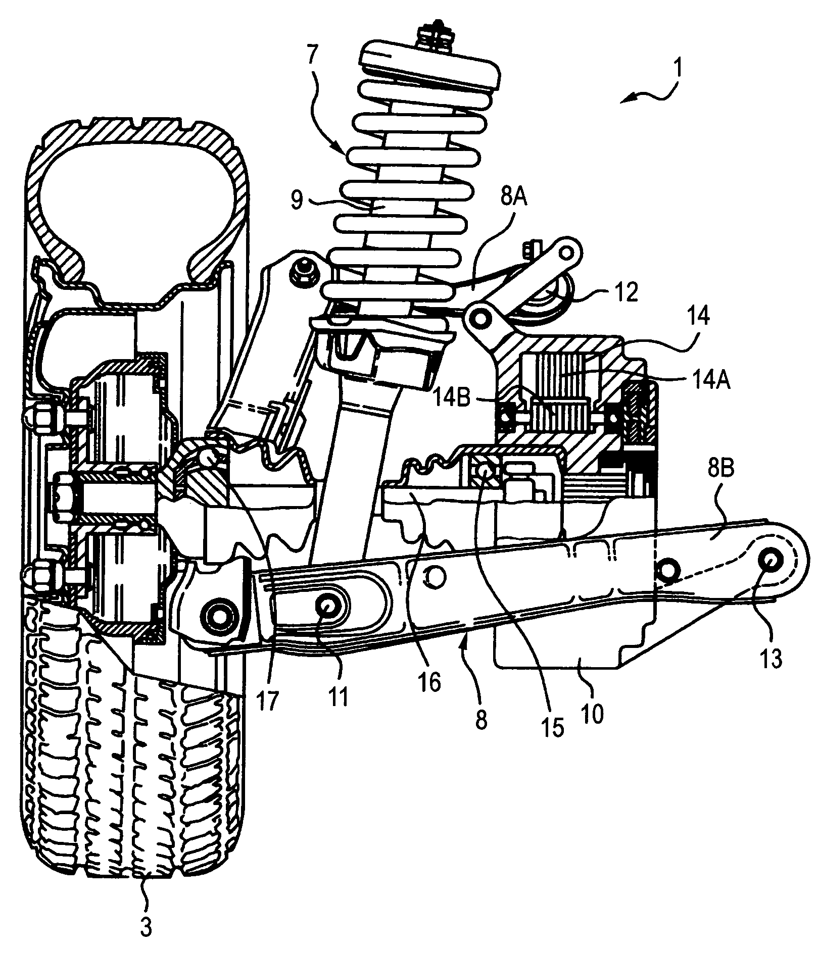
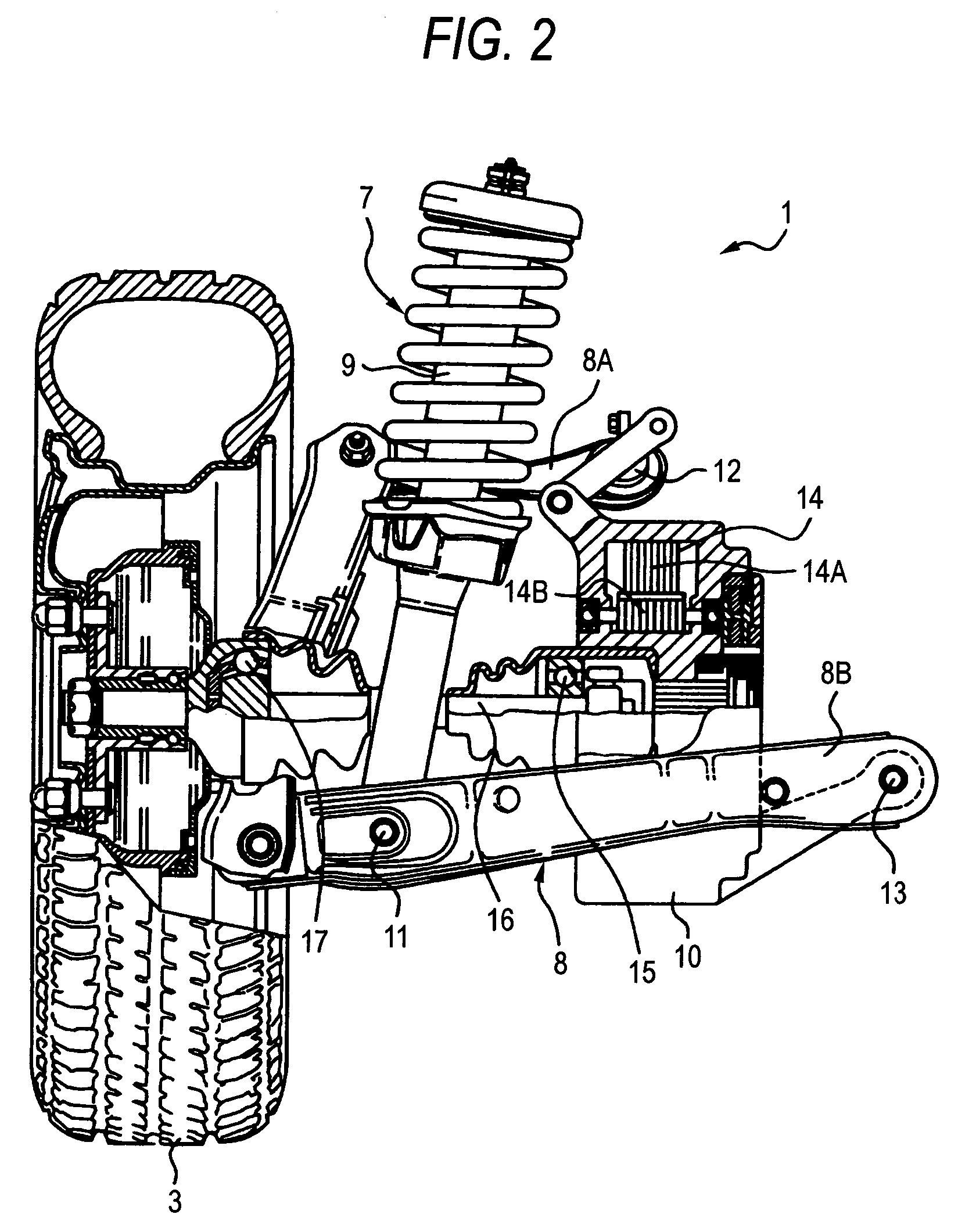
[0019]According to the construction, when vibrations and / or shocks are applied to the drive wheel from the outside, the drive wheel moves vertically via the resilient member and the first link mechanism portion of the suspension. Then, since the second link mechanism portion is connected to the vehicle body side connecting portion of the first link mechanism portion, when the drive wheel moves vertically as is described above, the electric motor fixedly attached to the second link mechanism portion performs symmetrically vertical movements relative to the vertical movements of the drive wheel, whereby inertia energy resulting from the vertical movements of the drive wheel and inertia energy resulting from the vertical movements of the electric motor are offset against each other, whereby the unsprung weight of the suspension can be reduced.

Problems solved by technology

Incidentally, in this related art, since the rear motors are disposed by making use of a space between the left and right drive wheels, a space for disposing a fuel tank (a gasoline tank) is reduced by a space occupied by the motors, leading to a problem that disposing an enlarged fuel tank is difficult.
As a result, the weight of a lower side of the suspension 103 or a so-called unsprung weight is increased, and the follow-up properties relative to irregularities on the road surface at the time of running are deteriorated, leading to a problem that the riding comfort is deteriorated.

Method used


Image

  • Vehicle with electric motors
  • Vehicle with electric motors
  • Vehicle with electric motors

Examples


Embodiment Construction

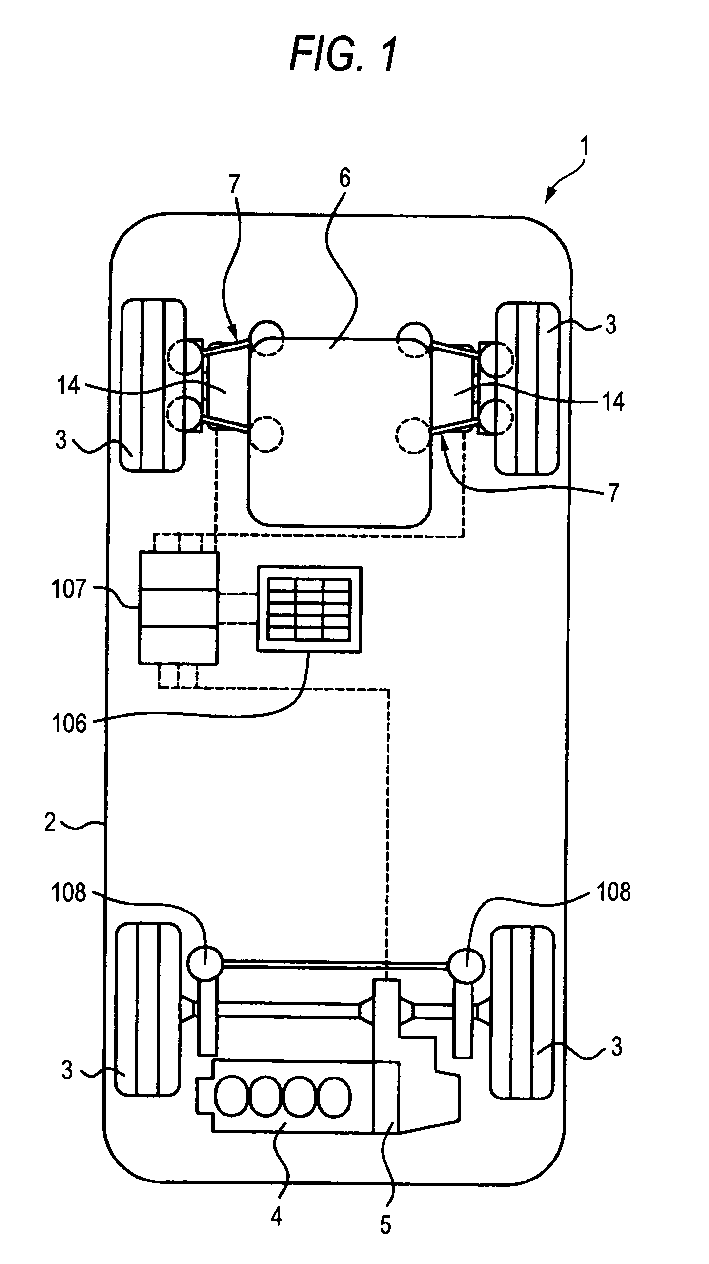
[0031]Referring to FIGS. 1 to 5, a mode for carrying out the invention will be described in detail by taking as an example a case where a vehicle with electric motors according to an embodiment of the invention is applied to a four-wheel drive vehicle. Note that, in this embodiment of the invention, like reference numerals are given to constituent elements which are like to those described with reference to the related art above, and the description thereof will be omitted.

[0032]FIG. 1 is a schematic diagram illustrating the construction of a hybrid four-wheel drive vehicle according to an embodiment of the invention, and FIG. 2 is a partially enlarged diagram illustrating an electric motor, a drive wheel and a suspension at a rear of the vehicle. Additionally, FIG. 3 is a schematic diagram illustrating a state in which a vehicle body is attached to the suspension shown in FIG. 2, and FIG. 4 is a schematic construction diagram illustrating a state in which the vehicle body shown in ...


PUM


Abstract

A first link mechanism of a suspension is provided at a rear end portion of a vehicle for connecting a drive wheel to a vehicle body, so that the drive wheel performs vertical movements relative to the vehicle body via the first link mechanism. In addition, a shock absorber is attached to a lower arm of the first link mechanism for resiliently supporting the drive wheel relative to the vehicle body. Furthermore, a second link mechanism is provided on the upper arm and the lower arm of the first link mechanism which performs symmetrically vertical movements relative to the vertical movements of the first link mechanism, and a motor is integrally attached to the second link mechanism, whereby inertia energy resulting from the vertical movements of the drive wheel and inertia energy resulting from the vertical movements of the motor are made to be offset against each other.

Description

BACKGROUND OF THE INVENTION[0001]The present invention relates to a vehicle with electric motors which has electric motors functioning at least as drive sources.[0002]Among related vehicles with electric motors, there is a hybrid four-wheel drive vehicle, for example, which installs an engine and electric motors (hereinafter, referred to as motors). In this hybrid four-wheel drive vehicle, the engine and the electric motor are installed, for example, at a front end thereof so that front wheels are driven using the engine and the motor so installed. In addition, the other motors are installed at a rear end of the vehicle so that rear wheels are driven using these motors.[0003]In the related hybrid four-wheel drive vehicle of this type, the front motor is allowed to function as a generator when braking. Namely, when braking, kinetic energy is converted into electric energy (regenerative energy), which can be stored (charged) in a high voltage battery which is provided separately from ...

Claims


Application Information

Patent Timeline
IPC IPC(8): B60K1/02B60G3/20B60G3/22B60G7/02B60G13/16B60K7/00B60K17/22B60K17/356
CPCB60G3/20B60G3/22B60G7/02B60G13/16B60K6/26B60K6/32B60K6/48B60K7/0007B60K17/356B60G2200/144B60G2200/17B60G2200/422B60G2202/25B60G2202/312B60G2204/129B60G2204/19B60G2204/421B60G2204/422B60G2300/50B60K17/043B60K17/22B60K2007/0053B60K2007/0061B60L2220/46H01M8/04201H01M2250/20Y02T10/6221Y02T10/6265Y02T90/34Y02T90/32Y02T10/62Y02T90/40Y02E60/50
Inventor AMANUMA, HIROKATSU
Owner HONDA MOTOR CO LTD
Learn More