Method and system for measuring differential scattering of light off of sample surfaces

Active Publication Date: 2006-10-10
LOCKHEED MARTIN CORP
View PDF1 Cites 20 Cited by
  • Summary
  • Abstract
  • Description
  • Claims
  • Application Information

AI Technical Summary

Benefits of technology

[0013]Numerous benefits may be achieved using the present invention over conventional techniques. For example, the invention provides for estimating differential-scattering profiles from surfaces, wherein the differential-scattering profiles are continuous solutions between specular and non-specular regions of scattered electromagnetic radiation scattered from a surface. Continuous differential-scattering profiles may be used to build improved optical systems, such as lenses and telescopes, that have reduced scattering or for which scattered radiation can be compensated for to lower the deleterious affects of the scattered radiation. Continuous differential-scattering profiles may also be used to build improved computer graphics programs (e.g., computer game graphics) to more accurately represent electromagnetic radiation reflected form graphical computer objects. Depending on the specific embodiment, there can be one or more of these benefits. These and other benefits can be found throughout the present specification and more particularly below.

Problems solved by technology

For example, stray light in the lens of a camera can cause photographic images to be formed that have aberrant light features that were not present in a photographed scene.
However, compensating empirically or intuitively for the shortcomings of known models of scattering tends to be relatively time consuming and often costly as technicians and / or engineers often fill in manually, regions for which known scattering models break down.
Addition steps of intuitive and / or empirical processing for isolating scattering information from lab setup information is often costly, time consuming, and may produce less than optimal results.

Method used


Image

  • Method and system for measuring differential scattering of light off of sample surfaces
  • Method and system for measuring differential scattering of light off of sample surfaces
  • Method and system for measuring differential scattering of light off of sample surfaces

Examples


Embodiment Construction

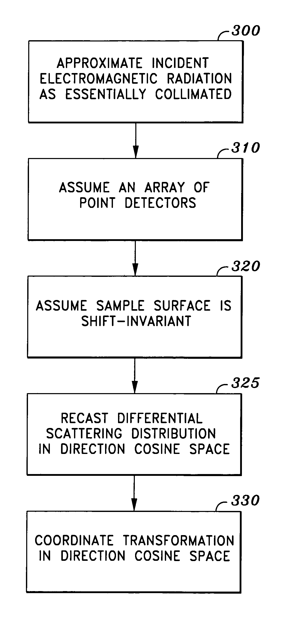
[0027]The present invention provides an optical system, and more particularly provides a method and system for predicting the directions and intensities at which light scatters from a surface, such that a scattering prediction includes a substantially continuous solution over a set of scattering angles that includes specular and non-specular scattering angles, wherein the scattering prediction may be used to generate improved optical systems and improved scattering simulations.

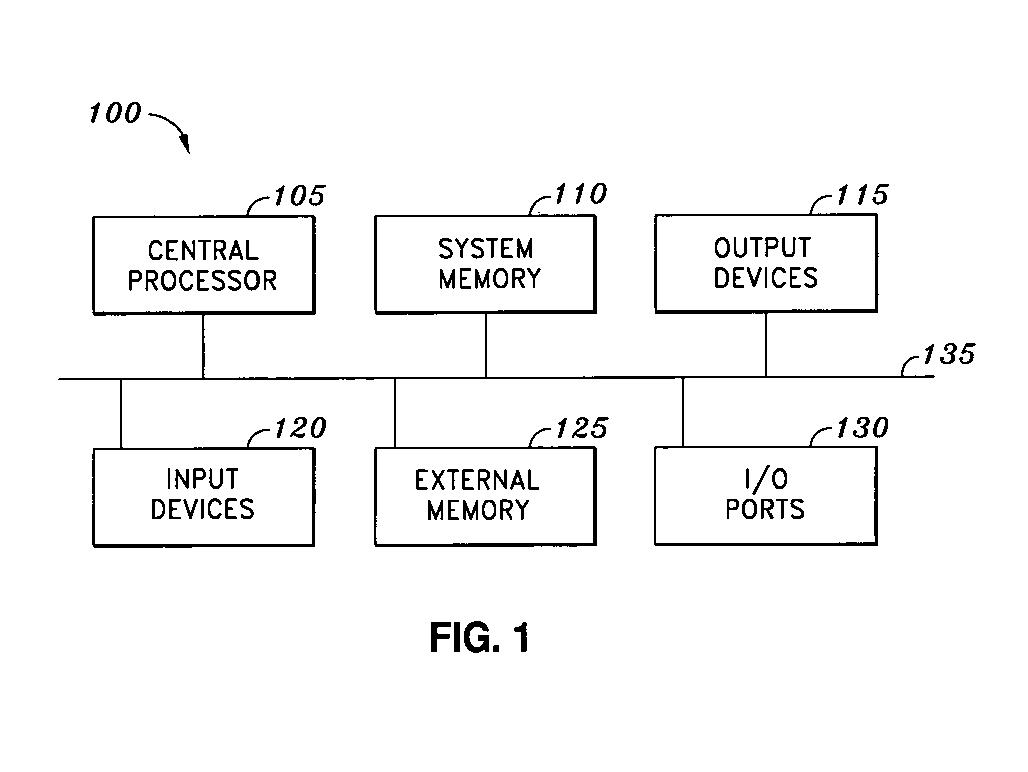
[0028]FIG. 1 is a block diagram of a computer system 100 in which embodiments of the present invention may be implemented. A specific embodiment of the invention is implemented on a computer system 100 having a processor 105, a system memory 110, output devices 115, input devices 120, a disk memory 125, I / O (input output) ports 130 and an interconnecting device 135. Processor 105 may be implemented in a variety of formats, such as, but not limited to, a microprocessor, a microcontroller, a microcomputer, embed...


PUM


Abstract

A method is provided for estimating scattering and includes providing a distribution expression that includes first, second, and third integrals over a source solid angle, a sample area, and detector solid angle respectively, and an integrand that includes a differential-scattering profile; approximating the first and second integrals to be the second integral, wherein the source electromagnetic radiation is approximated to be collimated; approximating the second and third integral to be the third integral, wherein a detector for detecting the electromagnetic radiation scattered from the surface is approximated to be a point detector; transforming the coordinates of the third integral over detector solid angle to be a fourth integral over a single dimension in cosine space, wherein the surface is approximated to be shift invariant; differentiating the fourth integral with respect to the single dimension to generate the differential-scattering profile; and generating an optical system design based on the differential-scattering profile.

Description

CROSS-REFERENCES TO RELATED APPLICATIONS[0001]This application claims priority to U.S. Provisional Patent Application 60 / 429,181, filed Nov. 25, 2002, titled METHOD AND SYSTEM FOR MEASURING DIFFERENTIAL SCATTERING OF LIGHT OFF OF SAMPLE SURFACES, and is incorporated by reference herein for all purposes.BACKGROUND OF THE INVENTION[0002]The present invention relates generally to an optical system, and more particularly related to a method and system for predicting the directions and intensities at which light scatters from a surface, such that a scattering prediction includes a substantially continuous solution over a set of scattering angles that includes specular and non-specular scattering angles, wherein the scattering prediction may be used to generate improved optical systems and improved scattering simulations.[0003]Scattering of stray light in optical devices, such as lenses, telescopes and the like, is a phenomenon that optical designers generally prefer to reduce. Stray ligh...

Claims


Application Information

Patent Timeline
IPC IPC(8): G01N21/47
CPCG01N21/47G01N2021/4711
Inventor JONES, BRIAN B.
Owner LOCKHEED MARTIN CORP
Why Eureka
Try Eureka