
Stabilized infrared source for infrared spectrometers

Active Publication Date: 2006-10-10
THERMO ELECTRONICS SCI INSTR LLC
View PDF26 Cites 23 Cited by
  • Summary
  • Abstract
  • Description
  • Claims
  • Application Information

AI Technical Summary

Benefits of technology

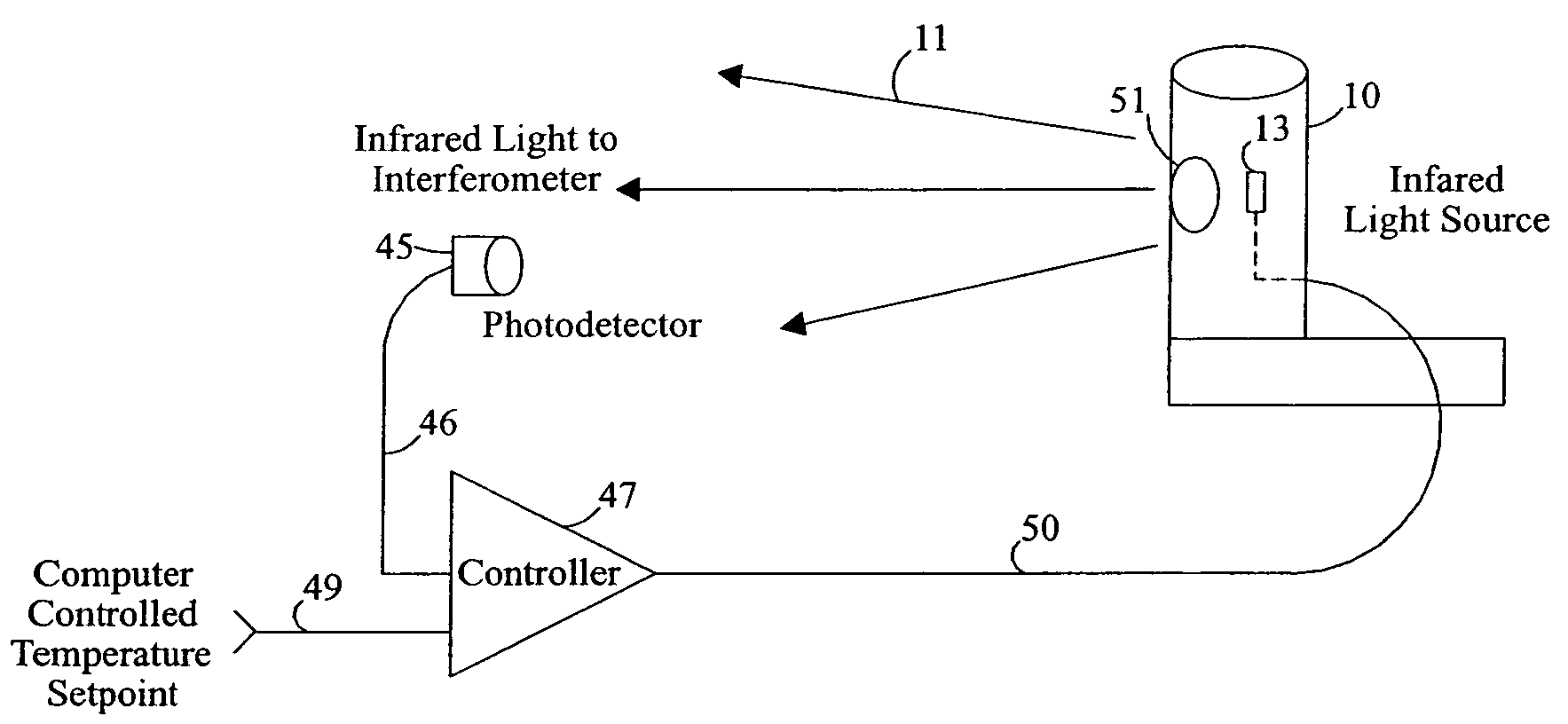
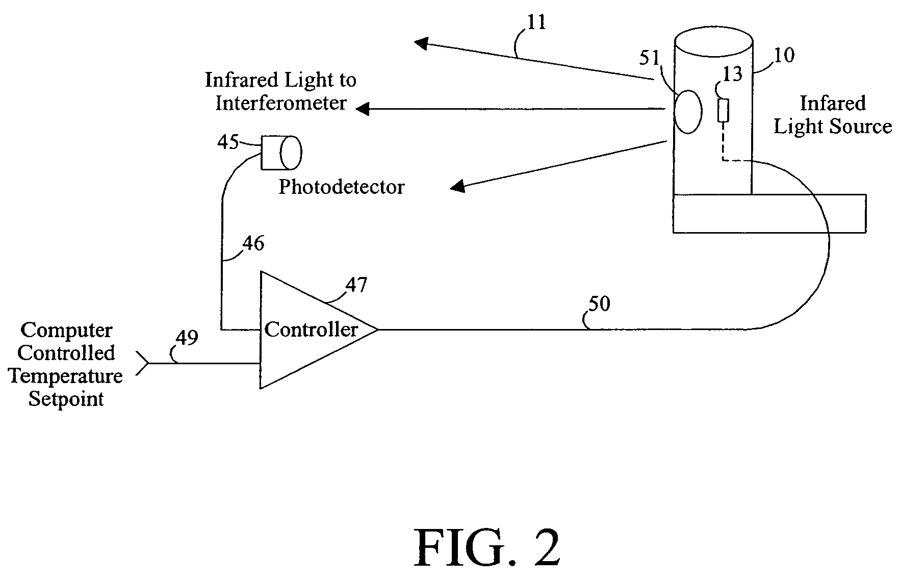
The invention is an infrared spectrometer that has a stable infrared output beam that is controlled to a desired intensity. This ensures that measurements made by the spectrometer at different times are more accurate and repeatable. The infrared source system includes an infrared source element and a light detector. A feedback control loop receives a signal from the detector and is connected to the source element to maintain the intensity of the light output from the source element at a selected level. This reduces short-term fluctuations in source output and changes in source output intensity over time. The invention also allows a longer source lifetime, reduces the temperature of the source when the spectrometer is in a standby condition, and maintains the source output at a desired light intensity level without accommodating the normal variability in the operating characteristics between sources. This increased lifetime permits increased use of an enhanced source mode where the source is heated to an above normal temperature to provide a higher light intensity output that may be useful to obtain good data from a weakly responsive sample being examined by the spectrometer.

Problems solved by technology

Thus, each individual source can be operated at the lowest temperature necessary to provide the desired output light intensity level, rather than being operated to provide sufficient light output from the least efficient source.

Method used


Image

  • Stabilized infrared source for infrared spectrometers
  • Stabilized infrared source for infrared spectrometers
  • Stabilized infrared source for infrared spectrometers

Examples


Embodiment Construction

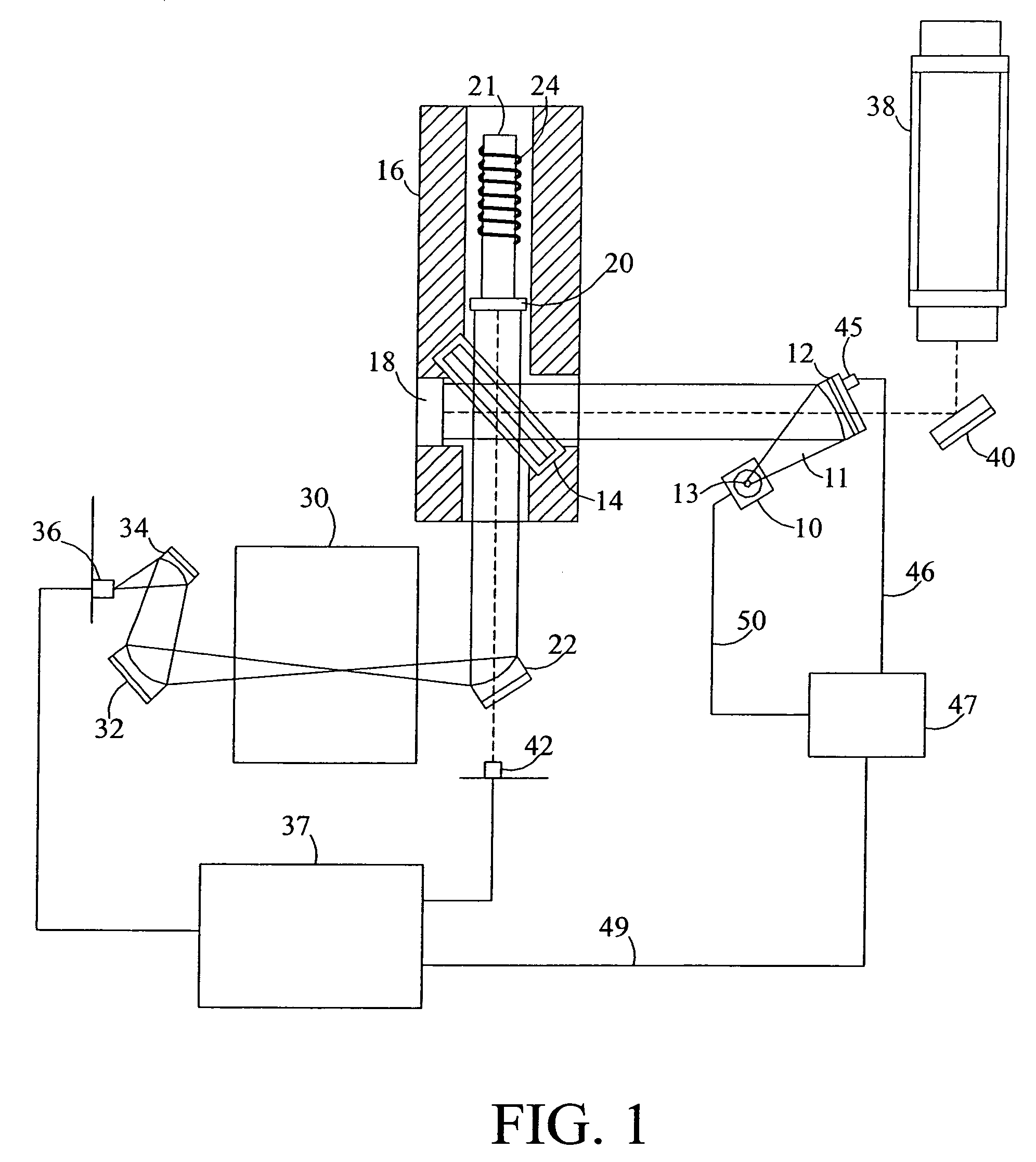
[0016]For purposes of illustrating the invention, the optical layout of a typical FTIR spectrometer system using a Michelson interferometer is shown in schematic form in FIG. 1. It is understood that such spectrometer systems can be laid out in many different geometries and with various additional features, and the present invention may be utilized in any such various embodiments of spectrometer systems. In the spectrometer system of FIG. 1, an infrared source 10 provides an output beam of light 11 from a source element 13 that is reflected off of a mirror 12, towards a beam splitter 14 within an interferometer housing 16. The light in the beam reflected from the mirror 12 which passes through the beam splitter 14 is then reflected by a reflecting mirror 18 which is located in the optical path of the beam coming from the mirror 12. A light path is formed which is perpendicular to the light path between the mirrors 12 and 18 by recombining light from the first beam with light partial...


PUM

PropertyMeasurementUnit
temperaturesaaaaaaaaaa
operating temperaturesaaaaaaaaaa
gate voltageaaaaaaaaaa

Abstract

An infrared spectrometer includes an infrared source system that is stabilized to provide a substantially constant output light intensity. The infrared source system includes a source element adapted to receive electrical power and to emit light at an intensity related to the electrical power received by the source element. A light detector is mounted in position to receive light emitted from the source element and to provide an output signal related to the intensity of the light received by the detector. A feedback control loop receives the signal from the detector and provides electrical power to the source element to maintain the intensity of the light output from the source element at a selected level as detected by the detector.

Description

FIELD OF THE INVENTION[0001]This invention pertains generally to the field of infrared spectrometers and particularly to infrared sources utilized in Fourier transform infrared spectrometers.BACKGROUND OF THE INVENTION[0002]Fourier transform infrared (FTIR) spectrometers are utilized in the analysis of chemical compounds. In these instruments, an infrared source provides a beam of infrared radiation having a band of infrared wavelengths which is passed into an interferometer, typically a Michelson interferometer, and is modulated before being passed through or reflected from the sample to be analyzed. The beam is then directed to a detector. The interferometer modulates the radiation received by it to provide an output beam in which many narrow ranges of infrared wavelengths are typically reduced or enhanced in intensity, with the affected range of wavelengths changing periodically over time. The time correlated output signal from the detector is analyzed by Fourier transformation t...

Claims


Application Information

Patent Timeline
Patent Type & Authority Patents(United States)
IPC IPC(8): G01B9/02G01J1/32G01J3/10G01N21/35
CPCG01J1/32G01J3/108G01J3/0243G01N2021/3595
Inventor COFFIN, JOHN M.BADEAU, ROBERT R.DAUN, MICHAEL R.
Owner THERMO ELECTRONICS SCI INSTR LLC
Learn More