Method of making high performance optical edge and laser-line filters and resulting products

a technology of laser-line filter and optical edge, which is applied in the field of making optical edge filter and laser-line filter, can solve the problems of not being as forgiving, physical softness, and easy to scratch or damage, and achieves accurate deposition duration, high transmission in the passband, and narrow transmission bandwidth

Active Publication Date: 2006-10-10
IDEX HEALTH & SCI
View PDF7 Cites 36 Cited by
  • Summary
  • Abstract
  • Description
  • Claims
  • Application Information

AI Technical Summary

Benefits of technology

[0035]These problems are addressed and a technical solution achieved in the art by high performance optical edge filters, high performance laser-line filters, and methods of making the same according to an embodiment of the present invention. In particular, the optical edge filters have an edge steepness less than about 0.8% as measured by dividing (a) the edge width from the 50% transmission wavelength to the optical density 6 (“OD6”) wavelength by (b) the 50% transmission wavelength. The optical edge filters also have an average transmission above about 95%. The laser-line filters have an extremely high transmission in the passband (greater than 90%), an extremely narrow transmission bandwidth, and achieve blocking with an optical de...

Problems solved by technology

The scattered excitation light would not only swamp the analyzer, it would also excite spurious Raman scattering in a collection fiber.
In addition, the steeper the slope, the greater the amount of shifted light from the sample that will reach the analyzer.
Soft coatings imply literally what the name suggests—they are physically soft and can be readily scratched or damaged.
They are fairly porous, which also means they tend to be hygroscopic (absorb water vapor) leading to dynamic changes in the film index and hence the resulting filter spectrum in correlation to local humidity.
This problem, coupled with the more difficult to control deposition rates and overall processes of high-melting-temperature oxides, leads to much more stringent requirements on the layer-thickness control techniques to achieve a reasonable level of layer thickness accuracy for good edge steepness and high, low-ripple transmission.
This technique is accurate and useful for layers of arbitrary thickness, but it is cumbersome, especially for filters comprised of at least many 10's of layers.
However, because small layer errors lead to large variations in the abs...

Method used


Image

  • Method of making high performance optical edge and laser-line filters and resulting products
  • Method of making high performance optical edge and laser-line filters and resulting products
  • Method of making high performance optical edge and laser-line filters and resulting products

Examples


example 1

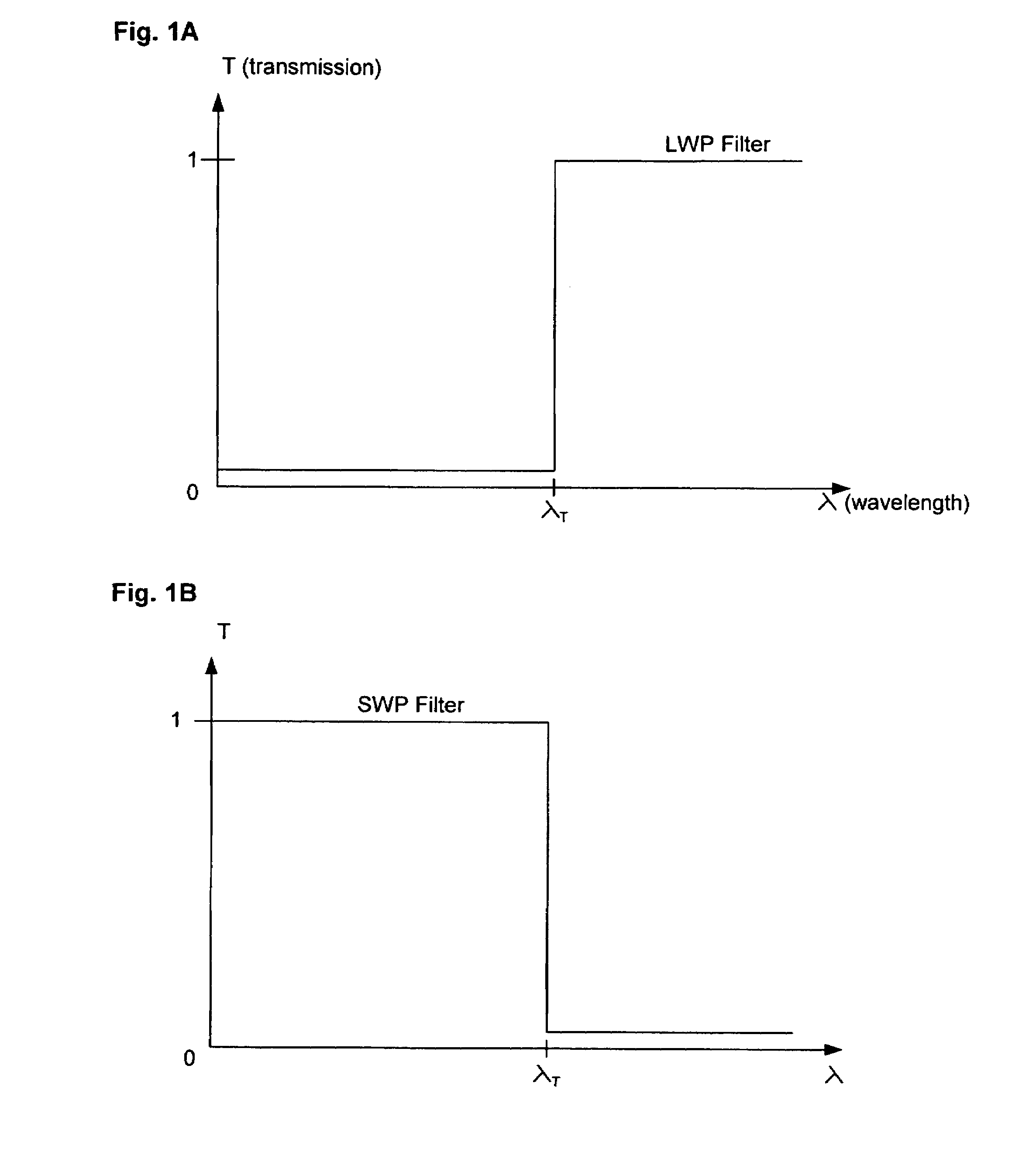
Long-Wave-Pass Edge Filter

[0114]A steep-edge LWP filter for a 532 nanometer laser-line was designed and fabricated in accordance with the LWP design strategy described above. The filter is to block the 532 nanometer laser light and light of lesser wavelength but to transmit light of longer wavelength. Appendix A gives the layer structure of the design. The optical thickness is given in units of quarter wavelengths (QWs) at the monitoring wavelength of 568 nanometers. The layers are counted from the substrate outward toward air. The substrate is BK7 glass, marketed by vendors such as Schott Glass. The design has 180 layers with a total metric thickness of 12.7 micrometers.

[0115]FIG. 9 shows the theoretical and measured transmission spectra of the resulting 532 nm LWP edge filter in accordance with an embodiment of the invention. Curve 901 is the theoretical spectrum, curve 902 is the measured spectrum and curve 903 is the laser wavelength line at 532 nm.

[0116]FIG. 10 illustrates the ...

example 2

Short-Wave-Pass Edge Filter

[0117]A steep-edge SWP filter was designed and fabricated in accordance with the SWP design strategy described above. The filter is to block the 532 nanometer laser light and light of greater wavelength but to transmit light of shorter wavelength. Appendix B provides the layer structure of the design. The optical thickness is given in QWs at the monitoring wavelength of 510 nm. The substrate is BK7 glass. The design has 180 layers with a total metric thickness of 15.1 micrometers.

[0118]FIG. 11 illustrates the theoretical and measured transmission spectra 1101 and 1102, respectively, of the realized SWP filter. The laser-line at 532 nm is shown at 1103.

[0119]FIG. 12 shows the theoretical and measured optical density spectra 1201 and 1202, respectively, and the laser-line 1203. The apparent “kink” that occurs between about OD 4 and 5 is due to the limitations of the measuring instrument, not the filter.

example 3

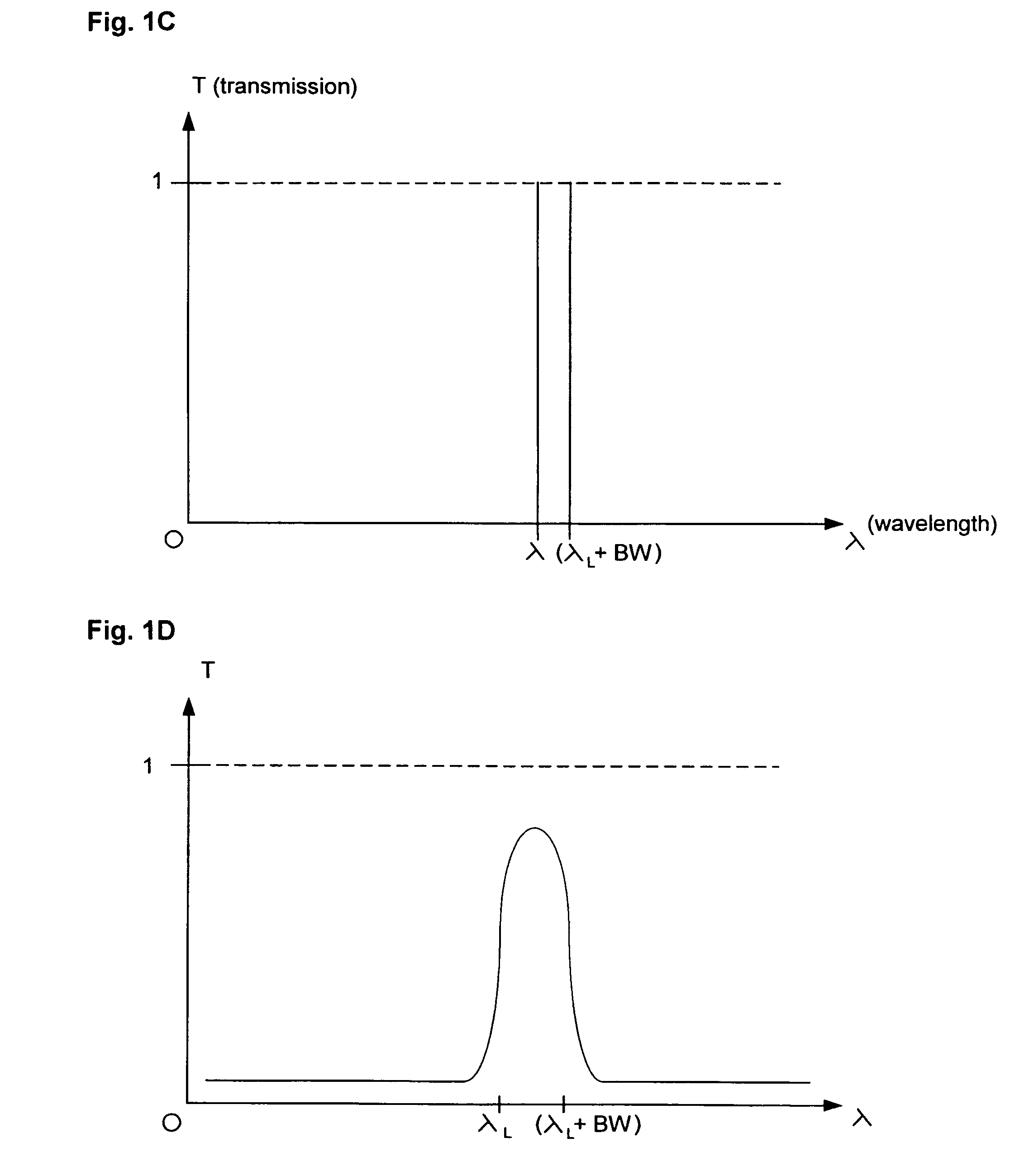
First Example of a Laser-Line Filter

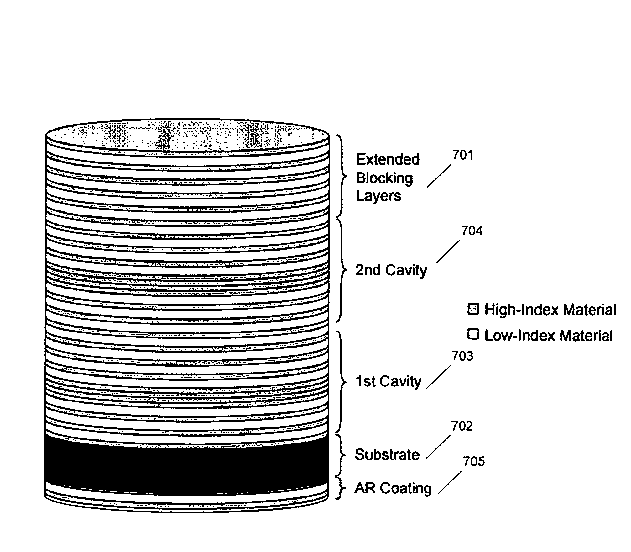
[0120]A laser-line filter having a combined multi-cavity Fabry-Perot and extended blocking coating on one side of the substrate and an anti-reflective coating on the other side of the substrate (FIG. 7, for example) was manufactured according to the processes described herein. This filter was a 532 nm filter whose coating structure is given in Appendix C. A graph showing both the designed 1301 and measured 1302 transmission spectrum for this filter is shown at FIG. 13.


PUM


Abstract

High performance optical edge and laser-line filters and methods of making the same are disclosed. The optical edge filters have an edge steepness greater than about 0.8% as measured by dividing (a) the edge width from the 50% transmission wavelength to the optical density 6 (“OD6”) wavelength by (b) the 50% transmission wavelength. The optical edge filters also have an average transmission above about 95%. The laser-line filters have an extremely high transmission in the passband (greater than 90%), an extremely narrow transmission bandwidth, and achieve blocking with an optical density (OD) greater than 5 at wavelengths that differ from the laser wavelength by less than 1% of the laser wavelength. The methods for making such filters accurately determine when deposition of each layer of the filter should terminate.

Description

CROSS REFERENCE TO RELATED APPLICATIONS[0001]This application claims the benefit of U.S. Provisional Application No. 60 / 578,978, filed Jun. 14, 2004, and is a continuation in part of prior U.S. patent application Ser. No. 10 / 840,134, filed May 6, 2004, now U.S. Pat. No. 7,068,430 B1, which claims the benefit of U.S. Provisional Application No. 60 / 468,245, filed May 6, 2003. The entire disclosures of U.S. Provisional Application No. 60 / 578,978, U.S. patent application Ser. No. 10 / 840,134, and U.S. Provisional Application No. 60 / 468,245 are hereby incorporated herein by reference.FIELD OF INVENTION[0002]This invention relates to methods of making optical edge filters and laser-line filters and also relates to the resulting improved filters.BACKGROUND OF THE INVENTION[0003]A. Optical Edge Filters, Laser-Line Filters, and Their Use[0004]Optical edge filters and laser-line filters are important components in systems for optical measurement and analysis including Raman spectroscopy and fl...

Claims


Application Information

Patent Timeline
IPC IPC(8): G02B5/28
CPCG02B5/288
Inventor ERDOGAN, TURANFOSS, JOSEPH T.WANG, LIGANG
Owner IDEX HEALTH & SCI
Why Eureka
Try Eureka