Panel for thin bricks and related systems and methods of use

a thin brick and panel technology, applied in the field of thin brick panel systems, can solve the problems of poor adhesion, limited surface area of foam panels available for mortar bonding, and inability to meet the requirements of construction,

Inactive Publication Date: 2006-10-17
OLD MILL BRICK LLC
View PDF23 Cites 50 Cited by
  • Summary
  • Abstract
  • Description
  • Claims
  • Application Information

AI Technical Summary

Benefits of technology

[0012]An object of the present invention is to provide a thin brick system facilitating a strong adhesive bond between the thin bricks and the foam panel by increasing the surface area of the thin bricks and foam panel available for contact with mortar.
[0013]Another object of the invention is to provide a thin brick system which has the flexibility to allow irregular sized and shaped bricks to be readily accepted and used by the system.
[0014]Accordingly, a thin brick panel system is provided, which comprises an expanded polystyrene foam panel having a front side and a back side. The front side defines a plurality of laterally extending channels. The channels are each defined by a pair of laterally extending spacing members or rails that are integrally formed with the panel. The panel is utilized to form a brick fascia on the exterior surface of a building or other structure. Of course, the system can be applied to new structures or existing structures. The panel system is configured to secure thin brick units to the building or structure in a manner that gives the appearance that full-sized bricks have been used. Use of a panel formed from expanded polystyrene instead of another material such as unexpanded polystyrene enables the channels to have irregular surfaces, which increases the surfaces area for bonding so that the adhesive can bond with optimal strength to the channels.
[0015]The thin brick units are inserted into the channels and each thin brick may rest on the laterally extending spacing member located at the bottom of each channel. A quick drying adhesive may be interposed between the brick units and the foam panel to bond the brick units directly to the foam panel. To further strengthen the bond between the thin bricks and the panel, mortar is introduced between the bricks. Because the height of the spacing members is less than the thickness of the thin bricks, mortar can be introduced on top of the spacing members and between the thin bricks. The top of the spacing members will preferably be flat or have a generally rectangular cross-section so as to maximize bonding with the mortar.
[0016]Moreover, the system is configured to provide for additional surface area for mortar bonding. The channels of the system are sized such that they are wider than the width of a typical thin brick. Accordingly, if the thin bricks are placed on the lower portion of the channels, for each normal brick there will be an open space between the top of the brick and the adjacent top spacing member. This space provides further surface area to which mortar can be applied. This increased surface area creates a strong bond between the mortar, the foam panel, and thin bricks, thereby remedying the problems seen in the prior art due to poor adhesion between thin bricks and foam panel. Not only do the wider channels provide advantageous bonding properties, but they also allow for the placement of irregular shaped and / or sized bricks, which cannot be used in snap-fit thin brick systems.

Problems solved by technology

Problems have arisen in this art due to poor adhesion between the thin bricks and the foam panels.
One of the problems identified early on with these “friction-fit” or “snap-fit” systems is the limited surface area of the foam panels available for mortar bonding.
This area of the foam panel is very small, and does not provide a strong bond between bricks and the panel.
Due to natural elements and weathering, thin bricks of such systems may become unstuck from the foam panels, causing an uneven, warped brick surface.
However, many strong adhesives disintegrate the polystyrene foam panel which is normally used in thin brick systems.

Method used


Image

  • Panel for thin bricks and related systems and methods of use
  • Panel for thin bricks and related systems and methods of use
  • Panel for thin bricks and related systems and methods of use

Examples


Embodiment Construction

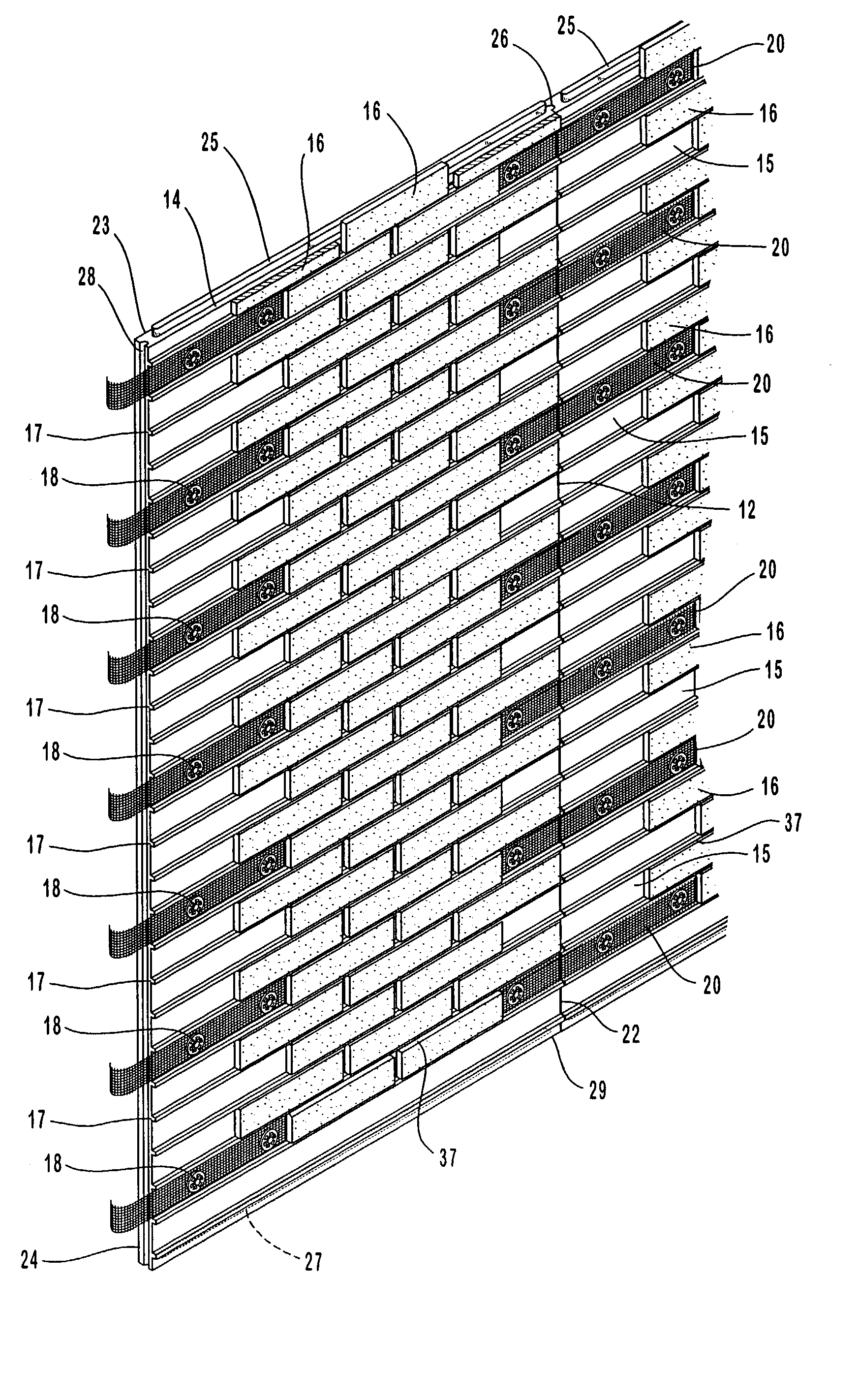
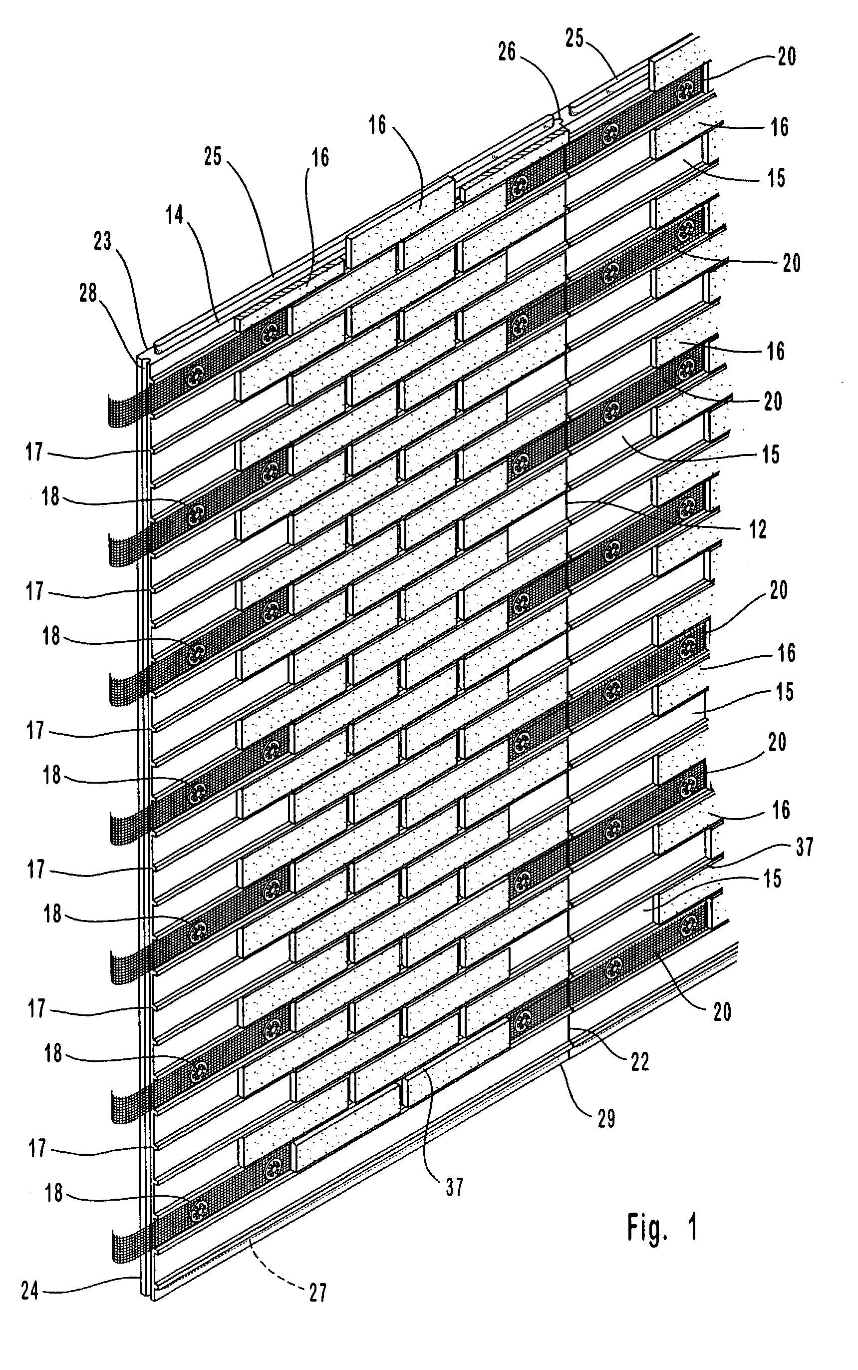
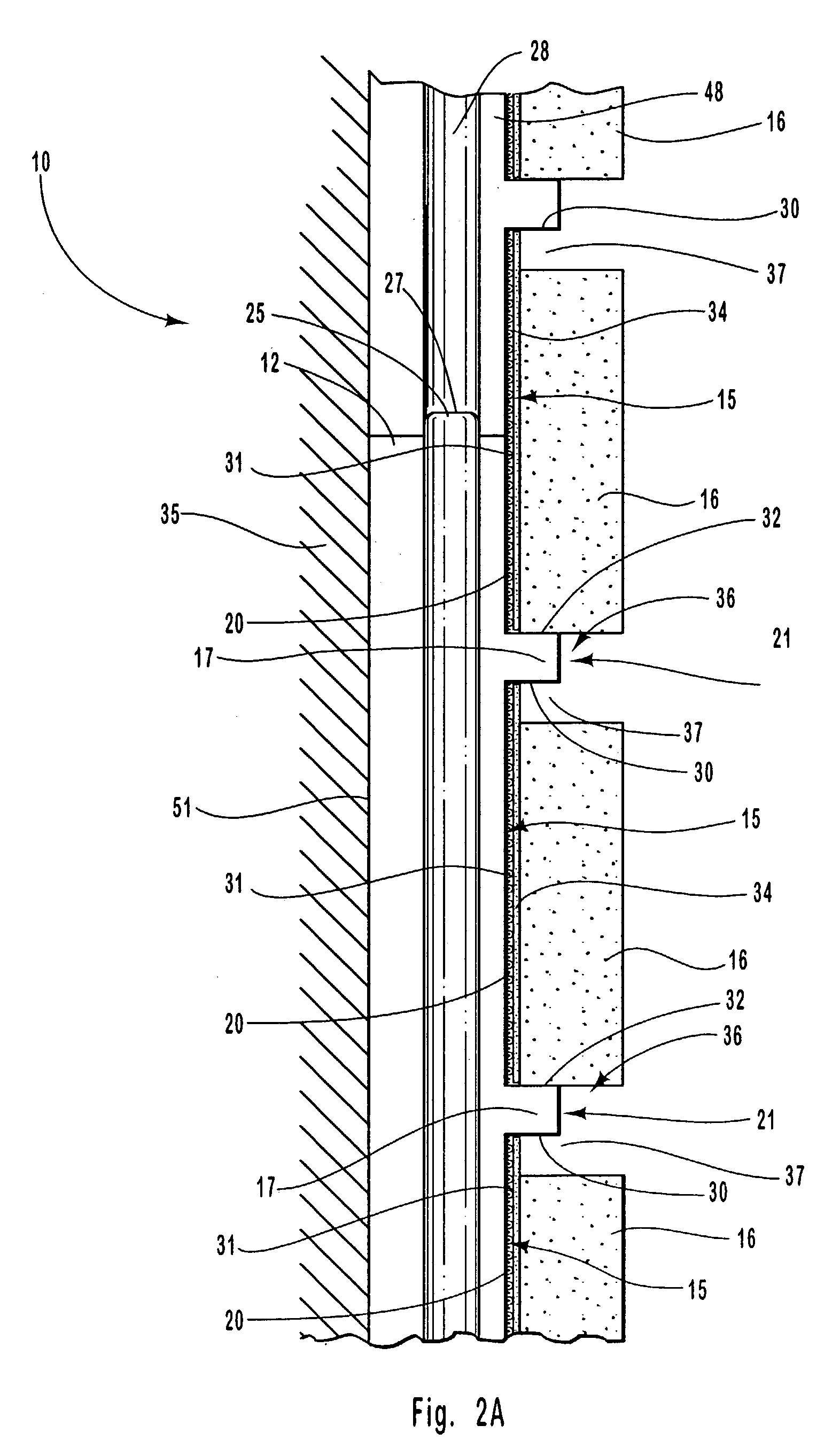
[0027]With reference to FIG. 1, the thin brick panel system of the present invention is indicated generally at 10. The system 10 is comprised of a panel 12, which may be formed from an expanded polystyrene insulation material, commonly referred to as beaded polystyrene foam, or the like. Expanded polystyrene panels provide for increased surface area for bonding between an adhesive, the thin brick units, and the panel. However, suitable panels for use in the system of the present invention may alternatively be formed from metals or other materials.

[0028]The foam panel 12 may be formed by cutting a sheet of expanded polystyrene foam, metal, or other material by any suitable means into the desired cross-sectional shape. Such material is flexible enough such that expansion and / or contraction due to temperature variations can be absorbed by the foam panel. In addition, beaded polystyrene foam can be manufactured in many shapes and sizes and does not have a thickness limitation, as is the...


PUM


Abstract

A thin brick panel system and method of forming a thin brick wall includes an expanded polystyrene foam panel having a plurality of laterally extending channels formed therein for receiving a plurality of thin brick units. The thin brick units are bonded to the channels in the foam panel and the seams between adjacent bricks are filled with a mortar that bonds to the foam panel. The foam panel may be attached to a substrate with an adhesive as well as fasteners. Strips of a mesh fabric may span several panels to bind the panels together to form a structurally sound thin brick wall.

Description

RELATED APPLICATIONS[0001]This is a continuation-in-part of U.S. application Ser. No. 09 / 781,350, filed on Feb. 12, 2001 now U.S. Pat. No. 6,516,578.TECHNICAL FIELD[0002]The present invention relates generally to building materials and structures. More particularly, it relates to thin brick panel systems used on home and building facades.BACKGROUND OF THE INVENTION[0003]Architectural thin face brick, commonly referred to as “thin brick,” is typically kiln-dried brick units that have height and width dimensions similar to those dimensions of conventional brick, but have a relatively small thickness. Thin brick systems are typically used as a decorative element to a new or existing architectural structure. These systems give structures the appearance of having “full” brick walls, while avoiding the associated expense. Many of these systems use a quick drying glue to adhere thin bricks to a foam panel. Mortar is then placed between the thin bricks to give the bricks structural integrit...

Claims


Application Information

Patent Timeline
Patent Type & Authority Patents(United States)
IPC IPC(8): E04C1/00E04F13/08E04F13/14
CPCE04F13/0862E04F13/147
Inventor HUNSAKER, GARRICK
Owner OLD MILL BRICK LLC
Why Eureka
Try Eureka