System, method, and apparatus for glide head calibration with enhanced PZT channel for very low qualification glide heights

a technology of glide head and calibration method, applied in the field of glide head calibration, can solve the problem of rms signal prematurely triggering media roughness contact, and achieve the effect of improving spin down on disk media roughness

Inactive Publication Date: 2006-10-17
HITACHI GLOBAL STORAGE TECH NETHERLANDS BV
View PDF19 Cites 15 Cited by
  • Summary
  • Abstract
  • Description
  • Claims
  • Application Information

AI Technical Summary

Benefits of technology

[0014]One embodiment of the present invention provides a new glide head calibration as a two-point fly height calibration on a disk media certifier. The first calibration point is a spin down on bump technique at a relatively high height (e.g., 8 to 10 nm). The second calibration point is an improved spin down on disk media roughness at a relatively low height (e.g., 3 to 4 nm). With two height data points, a fly height curve (i.e., linear velocity vs. height) of each head can be approximated very accurately. Depending on the design of the glide head, a linear or power regression curve can be used. Once this fly height curve is derived for each head, any fly height can be dialed-in by the disk media certifier for glide testing.
[0015]This new technique achieves glide fly heights below 8 nm and does so with improved tolerances. A significant advantage of this technique is that a fly height curve of each glide head can be generated directly on a disk media certifier. Another option is to rely on fly height curve data from an optical fly height certifier and transfer the data to the disk media certifier. This option has many correlation issues and can contribute to glide fly height tolerance errors up to about + / −2 nm. Another advantage is that the calibration is common across media products with the same form factor but different fly height requirements. Using the same high and low height calibration disks, products can be calibrated that require any glide head fly height between about 4 and 8 nm. In addition, the first calibration at some higher fly height retains all of the benefits of checking the glide head for proper flying characteristics and uniform PZT response.
[0016]One advantage of using glide PZT peak detection over PZT RMS for the media roughness measurement is improved accuracy. A defect on the track can cause the RMS signal to prematurely trigger media roughness contact. In the case of using the PZT peak detection, one defect on the track gets averaged out if the media roughness contact point is defined as contact with some large percentage of the entire track.
[0020]The channel enhancements needed for this new calibration technique include a new clock circuit and multiplexing capabilities. The new clock circuit allows the glide PZT peak detection to count the many glide head contacts with the media roughness. The clock circuit effectively adds artificial signal transitions when the media roughness multiple contacts cause the PZT signal to go into the DC shift phenomenon. Essentially, this forces the channel to trigger a software interrupt at the start of each sector and count if the PZT signal is still high. The multiplexer allows the PZT signal from the glide head to travel through the glide channel in either path, depending on the desired mode. It can operate in discreet defect detection mode or in media roughness measurement mode. Software can multiplex the channel to the discreet defect detection mode for the high fly height calibration, multiplex to media roughness measurement mode for the low fly height calibration, and then multiplex back to defect detection for glide testing.

Problems solved by technology

This option has many correlation issues and can contribute to glide fly height tolerance errors up to about + / −2 nm.
A defect on the track can cause the RMS signal to prematurely trigger media roughness contact.

Method used


Image

  • System, method, and apparatus for glide head calibration with enhanced PZT channel for very low qualification glide heights
  • System, method, and apparatus for glide head calibration with enhanced PZT channel for very low qualification glide heights
  • System, method, and apparatus for glide head calibration with enhanced PZT channel for very low qualification glide heights

Examples


Embodiment Construction

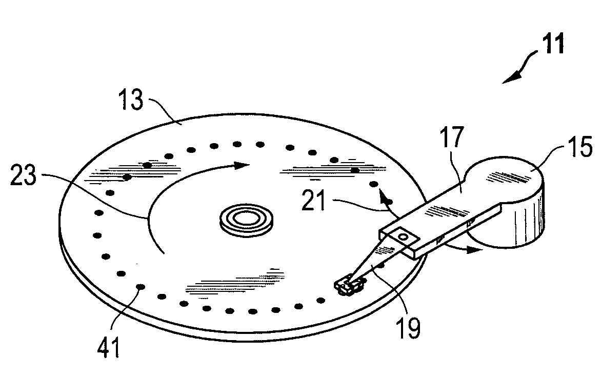
[0028]Referring to FIG. 1, one embodiment of an apparatus 11 for calibrating a glide head utilizes a rotating, magnetic disk 13 having a large plurality of tracks. The disk 13 also has a plurality of precisely formed glide bumps 41 that are used during the calibration process, as will be described below. Apparatus 11 comprises an actuator 15 with a movable arm 17 and a suspension 19 on one end. Arm 17 and disk 13 move in the directions indicated by arrows 21, 23, respectively. Arm 17 provides the seek motion when changing tracks on disk 13.

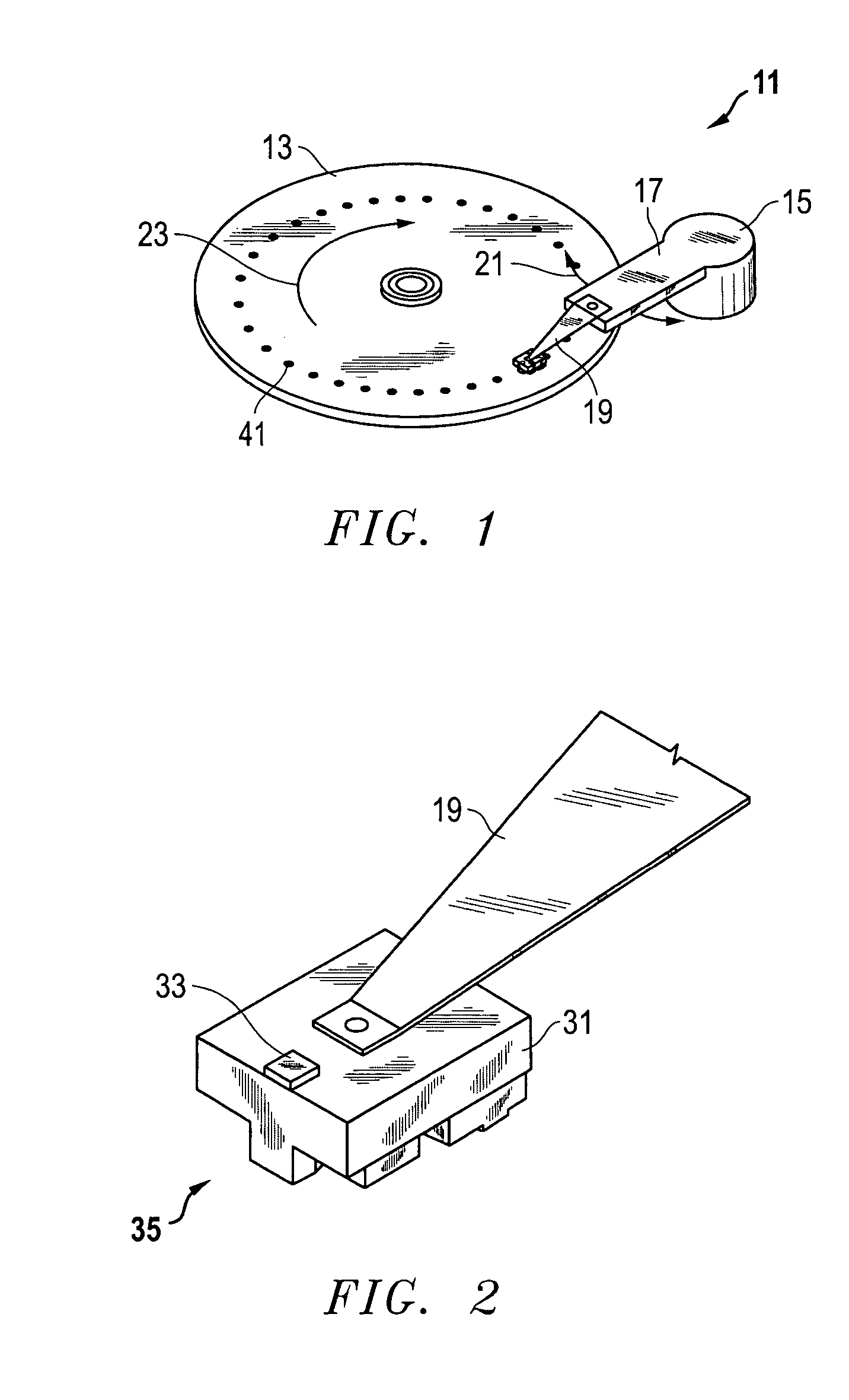
[0029]As shown in FIG. 2, a slider or flying / glide head 31 is bonded to the end of suspension 19. In the embodiment shown, glide head 31 is nano size (approximately 2050×1600×450 microns) and formed from ceramic or intermetallic materials. Glide head 31 may also be pico size (approximately 1250×1000×300 microns). Glide head 31 is pre-loaded against the surface of disk 13 (typically in the range two to ten grams) by suspension 19. It is glide head ...


PUM

PropertyMeasurementUnit
heightsaaaaaaaaaa
heightaaaaaaaaaa
heightsaaaaaaaaaa

Abstract

A glide head calibration technique uses two fly height calibrations on a disk media certifier. The first calibration point uses a spin down on bump technique at a first height, and the second calibration point uses a spin down on disk media roughness at a second lower height. With two height data points, a fly height curve of each glide head is approximated very accurately. Once the fly height curve is derived for each head, any fly height can be dialed-in by the disk media certifier for glide testing. This technique achieves glide fly heights between about 4 nm and 8 nm and does so with improved tolerances.

Description

BACKGROUND OF THE INVENTION[0001]1. Technical Field[0002]The present invention relates in general to improved calibration of glide heads and, in particular, to an improved system, method, and apparatus for measuring media roughness and combining that with spin down calibration to form a new and improved glide head calibration for media glide testing.[0003]2. Description of the Related Art[0004]Data access and storage systems comprise one or more storage devices that store data on magnetic or optical storage media. For example, a magnetic storage device is known as a direct access storage device (DASD) or a hard disk drive (HDD) and includes one or more disks and a disk controller to manage local operations concerning the disks. The hard disks themselves are usually made of aluminum alloy or a mixture of glass and ceramic, and are covered with a magnetic coating. Typically, two or three disks are stacked vertically on a common spindle that is turned by a disk drive motor at several t...

Claims


Application Information

Patent Timeline
Patent Type & Authority Patents(United States)
IPC IPC(8): G01B7/34G01B7/14G01B11/14G01B11/30G11B5/455G11B5/60
CPCG11B5/455G11B5/6005
Inventor CHU, NORMANDUAN, SHANLINGALINDO, PATRICIANGO, HANG FAILO, YUZHOU, NALIN
Owner HITACHI GLOBAL STORAGE TECH NETHERLANDS BV
Why Eureka
Try Eureka