Electronic throttle control device

a technology of electronic control device and throttle valve, which is applied in the direction of electrical control, process and machine control, etc., to achieve the effects of reducing power consumption of electric control mechanism, shortening the piping distance between the throttle valve and improving acceleration-deceleration of engin

Inactive Publication Date: 2006-10-17
MITSUBISHI ELECTRIC CORP
View PDF13 Cites 19 Cited by
  • Summary
  • Abstract
  • Description
  • Claims
  • Application Information

AI Technical Summary

Benefits of technology

[0011]A first object of the present invention is to provide an electronic throttle control device for use in a multi-cylinder engine, in which any complicated arrangement of mechanism is not required, and of which life is long, power consumption is small and acceleration-deceleration response is superior.
[0012]A second object of the invention is to provide an electronic throttle control device capable of reducing control burden on a microprocessor cooperating with a program memory acting as target throttle valve opening setting means.
[0013]A third object of the invention is to provide an electronic throttle control device capable of maintaining an appropriate air / fuel ratio and reducing poisonous exhaust gas even under the condition of performing an in take of which amount is different for each individual cylinder.
[0017]The mentioned feedback control circuit section is a control circuit section for on / off-controlling switching elements disposed on a power supply circuit of each of the motors so that a detection output of the throttle position sensors detecting a throttle valve opening is equal to the mentioned target throttle valve opening or the mentioned holding throttle valve opening, and in which control burden on the mentioned microprocessor is reduced by sequentially executing the valve opening control for the plural motors.
[0018]As described above, in the electronic throttle valve control device according to the invention, the throttle valve opening of the intake pipe for each cylinder or the intake pipe for each cylinder group is electrically controlled in response to a degree of stepping on the accelerator pedal, and an advantage is obtained such that acceleration-deceleration of the engine can be improved by shortening the piping distance between the throttle valve and the cylinder. Further, since the throttle valve opening is held at a certain value during steady running, another advantage is obtained such that power consumption of the electric control mechanism is reduced, and wear and tear of the opening and closing mechanism of the throttle valve is also reduced. Furthermore, since the control of throttle valve opening is sequentially subject to time-division processing so as not to overlap in each cylinder, control burden on the microprocessor is not increased, and it is possible to make all of a series of controls such as fuel injection control, ignition control, etc. simply with the use of just one microprocessor.
[0019]Since the motor control is sequentially carried out, a further advantages are obtained such that diameter of wire in the power supply system is prevented from being increased; current rating of power supply fuse is restrained from being increased; width of copper foil pattern of electronic substrate in the operation control apparatus is restrained from being increased; drive noise is prevented from being increased; and capacity of an anti-noise capacitor in the operation control apparatus is prevented from being increased.

Problems solved by technology

This is because controlling a small amount of intake air just by controlling an intake time using the intake control valve that performs the entire opening and closing operation becomes difficult during idling or the like, and it is necessary to suppress the entire intake amount by the throttle valve when accelerator pedal has been returned.

Method used


Image

  • Electronic throttle control device
  • Electronic throttle control device
  • Electronic throttle control device

Examples


embodiment 1

(1) Detailed Description of the Features of Embodiment 1:

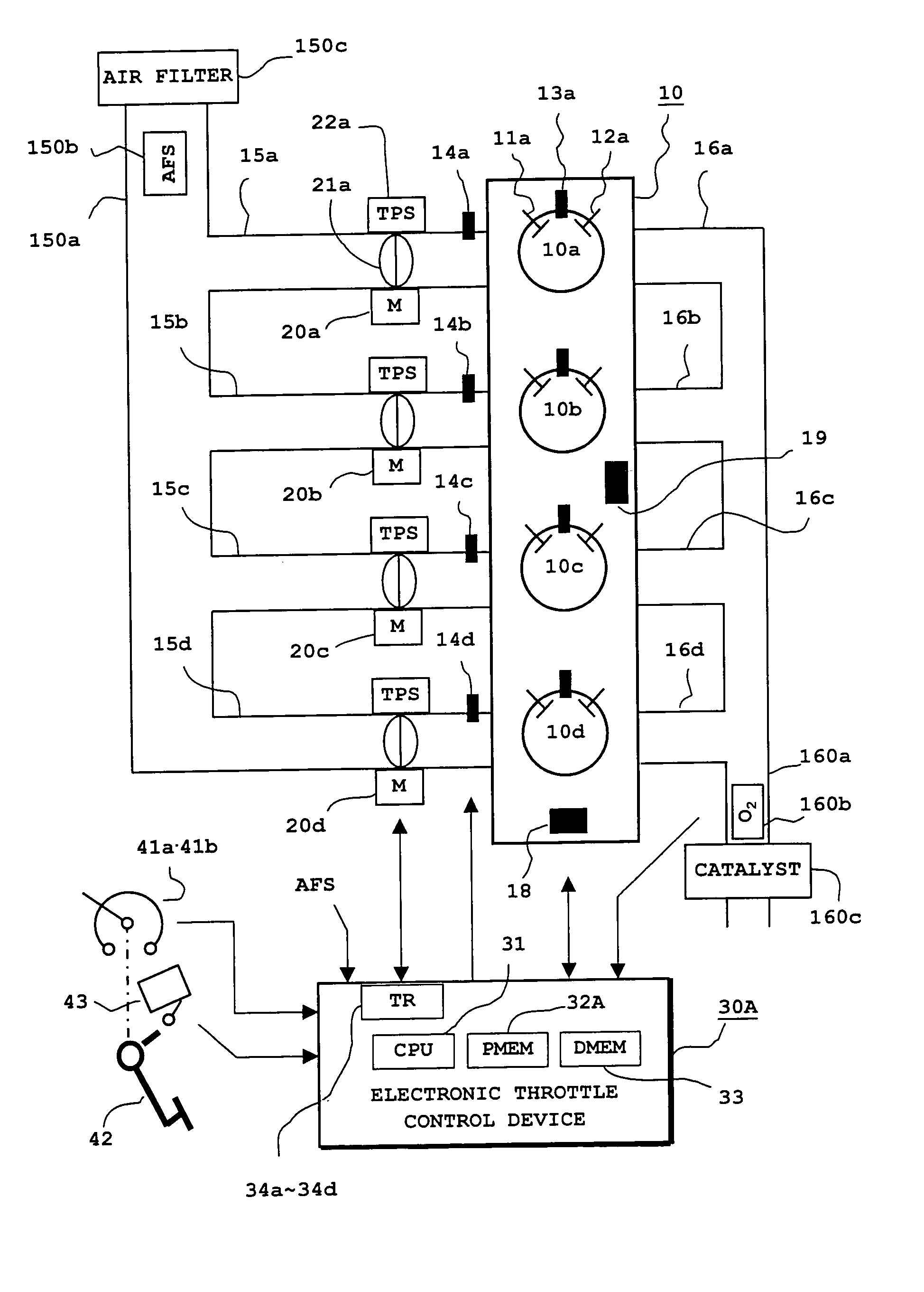
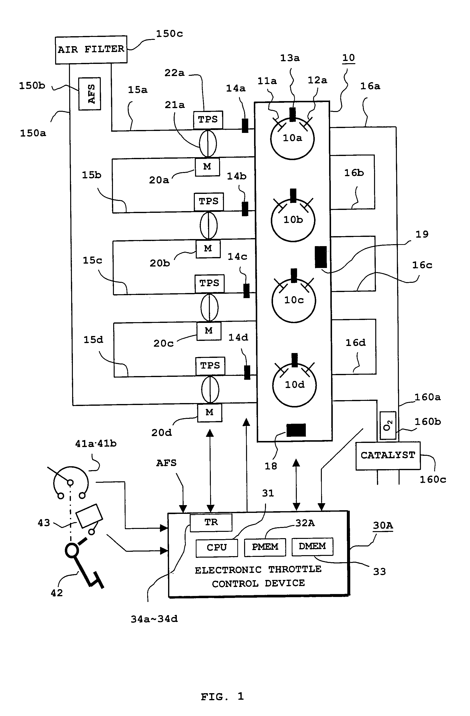
[0035]An electronic throttle control device for a multi-cylinder engine according to Embodiment 1 of the present invention is hereinafter described with reference to FIG. 1 showing an entire mechanism of the electronic throttle control device. Referring to FIG. 1, a multi-cylinder engine 10 is shown as a four-cylinder engine having cylinders 10a, 10b, 10c and 10d. The cylinders 10a to 10d are respectively provided with intake valves 11a to 11d and exhaust valves 12a to 12d each interlocking with turning of a crankshaft not illustrated. In the case where the multi-cylinder engine 10 is a gasoline engine, ignition plugs 13a to 13d are used. (In the drawing, indication of reference numerals 11a to 11d, 12a to 12d and 13a to 13d is omitted.)

[0036]Fuel-injecting electromagnetic valves 14a to 14d are disposed in the vicinity of the intake valves 11a to 11d. Intake pipes 15a to 15d disposed for each cylinder and communicating to the ...

embodiment 3

(1) Detailed Description of the Features of Embodiment 3:

embodiment 2

(1) Detailed Description of the Features of Embodiment 2:

[0135]An electronic throttle control device for a multi-cylinder engine according to Embodiment 3 of the invention is hereinafter described with reference to FIG. 11 showing an entire mechanism of the electronic throttle control device, focusing the differences from the foregoing Embodiment 1 shown in FIG. 1. Referring to FIG. 11, an operation control device 30C controlling the multi-cylinder engine 10 is mainly comprised of the microprocessor 31 containing a program memory 32c and a data memory 33, and drives motors 20x, 20y in response to the detection output of the accelerator position sensors 41a, 41b that detect a degree of stepping on the accelerator pedal 42. The operation control device 30C controls a valve opening of throttle valves 21x, 21y disposed on branch collecting pipes 150x, 150y, and controls operation timing and time period of the fuel injection valves 14a to 14d in response to the total intake amount detect...


PUM


Abstract

Intake throttle valves 21a to 21d disposed on the intake pipes 15a to 15d for each cylinder of a multi-cylinder engine 10 are provided with motors 20a to 20d for controlling valve opening of the intake throttle valves. The microprocessor 31 controls throttle valve opening in response to a degree of stepping on an accelerator pedal 42 in cooperation with a program memory 32A. The control of valve opening by each motor is sequentially subject to time division processing in the exhaust stroke of each cylinder, and a current valve opening is stored and held by a feedback control circuit section 39, 69B, 69C in the other strokes, thereby the control burden on the microprocessor being reduced.

Description

BACKGROUND OF THE INVENTION[0001]1. Field of the Invention[0002]The present invention relates to an electronic throttle control device that drives to open and close intake throttle valves of a multi-cylinder engine by means of a microprocessor cooperating with a program memory and, more particularly, to a simplified electronic throttle control device in which the mentioned intake throttle valves and throttle valve control motors are disposed at plural places for each cylinder or for each cylinder group and are controlled just by a single microprocessor.[0003]2. Description of the Related Art[0004]In the field of multi-cylinder engine, it has been known to arrange an operation control device in which an intake control valve is disposed in an intake passage of each cylinder, and intake amount for each cylinder is controlled by controlling a valve-opening time of this intake control valve. For example, according to the later-discussed Japanese Patent Publication (unexamined) No. 279698...

Claims


Application Information

Patent Timeline
Patent Type & Authority Patents(United States)
IPC IPC(8): F02D11/10G06G7/00
CPCF02D9/109F02D11/105F02D41/008F02D41/26F02D9/105F02D41/0002F02D2250/12
Inventor NAKAMOTO, KATSUYAHASHIMOTO, KOHJI
Owner MITSUBISHI ELECTRIC CORP
Why Eureka
Try Eureka