Bi-directional automotive cooling fan

Inactive Publication Date: 2006-10-17
MACKELVIE WINSTON
View PDF20 Cites 34 Cited by
  • Summary
  • Abstract
  • Description
  • Claims
  • Application Information

AI Technical Summary

Benefits of technology

[0031]Axial motor fan blades are produced in two forms: ‘push’ or ‘pull’ the choice depending on whether the fan is mounted in front of the radiator (push) or behind the radiator (pull). To ensure adequate engine cooling and air blocking capability with the present invention, the fan's blade design should be selected to maximize air flow dynamics in the reverse or forward blowing direction although a neutral design wou

Problems solved by technology

Due the rich fuel mixture which must be burnt, fuel consumption is higher, exhaust is dirtier and contains larger amounts of unwanted pollutants, and, the excess fuel dilutes the oil film lubricating the piston-cylinder surfaces causing excessive wear as well as contaminating the oil.
Once the engine has reached operating temperature it thereafter produces large amounts of unwanted waste heat that must be dissipated to prevent overheating.
However the engine surface now receives hot radiator air and so cannot be cooled as effectively as when driving at speed.
Further that hot air unwantedly heats the engine bay components and is then discharged beneath the vehicle's front portion wherefrom a portion of the hot air finds its way back to the front intake.
Moreover, during the fan's off interval, the engine bay or underhood compartment receives no cooling air and so the compone

Method used


Image

  • Bi-directional automotive cooling fan
  • Bi-directional automotive cooling fan

Examples


Embodiment Construction

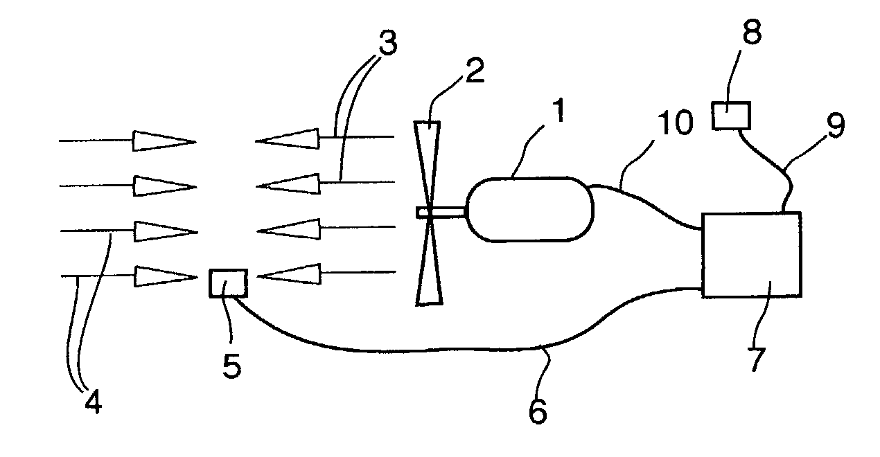
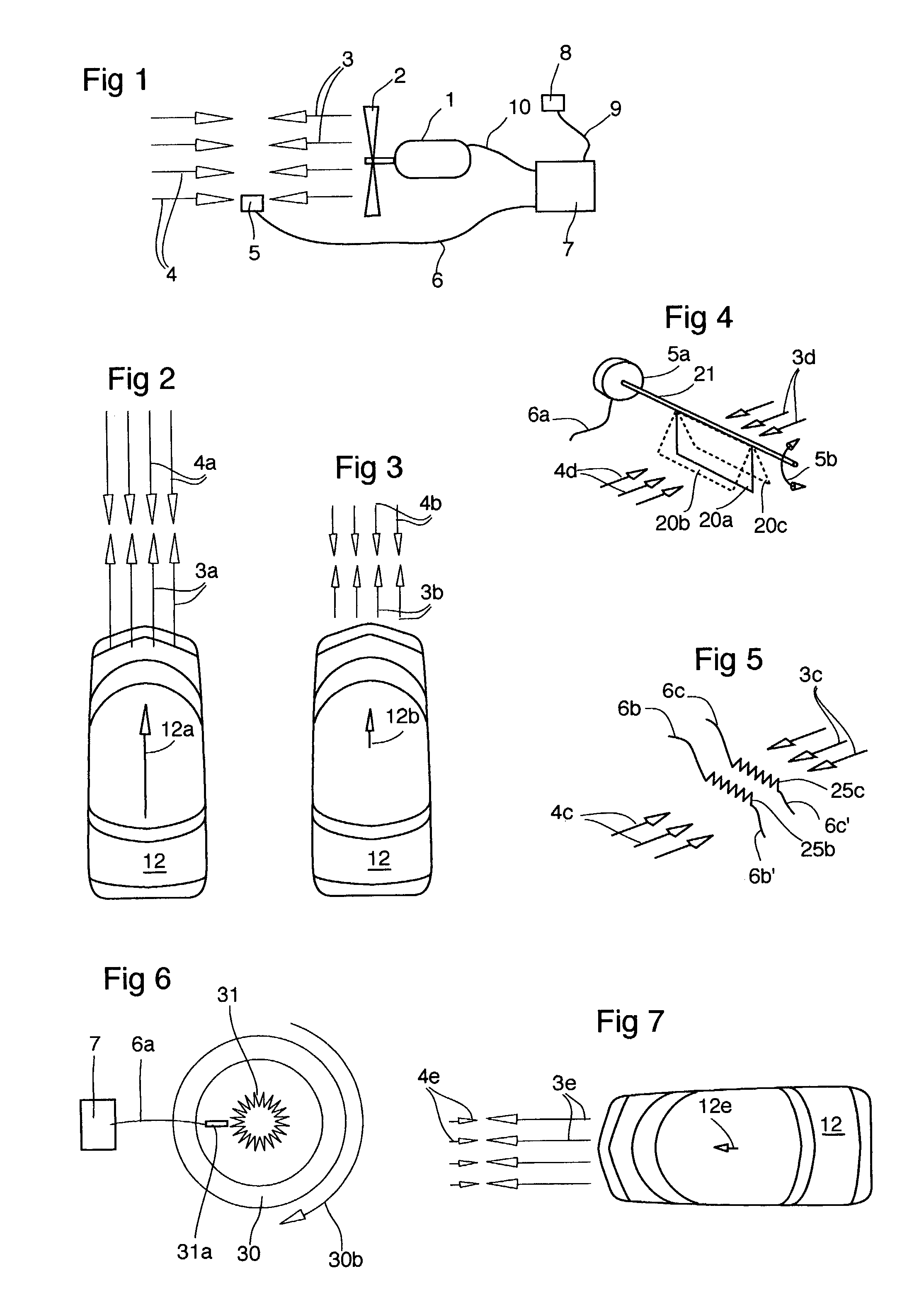
[0039]In FIGS. 1–5 and 7, air velocity / pressure is shown by arrow-headed straight lines wherein longer lines represent higher speed (or force) and arrowheads show direction of fan air flow 3 and ram air flow 4.

[0040]Referring to FIG. 1 electric motor 1 drives fan blades 2 in reverse mode creating a forward fan air flow 3 opposite in effect to the inlet ram air flow 4 created by vehicle's road speed. When flows (or pressures) 3 and 4 are equal and opposite, there is zero net air flow into engine bay (not shown) and onto cold engine. Fan motor 1 is powered by control circuit 7 through wire 10. Circuit 7 receives ‘too cold’ temperature signal from engine temperature sensor 8 via wire 9. In a preferred embodiment, control circuit 7 may also receive vehicle's road speed signal from vehicle road speed sensor 5 via wire 6. Vehicle road speed may be sensed from ram air speed (shown in FIGS. 1, 4, 5), electronically (one example shown in FIG. 6), or fan motor power variations (not shown). Wh...


PUM


Abstract

The instant invention pertains to a road vehicle's axial flow cooling fan which normally draws cooling air from in front of the vehicle and blows it into the engine bay. The instant invention includes a control circuit for the fan motor that provides variable speed and bi-directional, or reverse and normal, fan operation. Reverse fan operation blows air from the engine bay through the radiator and out the front of the vehicle, and normal fan operation blows into the engine bay. Two input sensors feed the control circuit, one for road speed of the vehicle and other for engine temperature. When the engine is below its operating temperature and the vehicle is moving, the fan is made to blows in reverse at a speed proportional to road speed so as to block cold ram air from entering and blasting onto a warming engine. This speeds engine warm-up to reduce emissions, improve fuel economy, and speed windshield defogging. The fan may also be made to blow in reverse when the engine is cold and the vehicle is stopped, in order that exhaust-heated air from the exhaust manifold behind the engine, may be drawn forward over the engine block to speed its warming. When the engine is above its operating temperature and the vehicle is idling or moving slowly, as in traffic, then the control circuit causes the fan to again blow in reverse cooling both the radiator and the engine bay components and preventing hot, noxious fumes from vehicles in front from being drawn into the vehicle. Blowing in reverse in traffic conditions also eliminates hot air looping back to the front of the car and drawn in through the radiator. As vehicle speed increases, the fan is made to revert to normal operation augmenting ram air flow through the radiator.

Description

[0001]The present application is a continuation-in-part of application Ser. No. 09 / 849,962 filed May 4, 2001, now abandoned which is a non provisional application of provisional application No. 60 / 203,072, filed May 9, 2000.FIELD OF THE INVENTION[0002]The instant invention uses engine temperature and vehicle road speed sensors that input to a fan motor control circuit to add both bi-directional rotation and speed of rotation control of the fan for the purpose of blowing air forwards and outwards from the front of the vehicle under certain driving conditions. Brush-type, direct current motors of the type that drive cooling fans, can be run in reverse by switching polarity.BACKGROUND OF THE INVENTION[0003]Cold engine operation has numerous disadvantages. Due the rich fuel mixture which must be burnt, fuel consumption is higher, exhaust is dirtier and contains larger amounts of unwanted pollutants, and, the excess fuel dilutes the oil film lubricating the piston-cylinder surfaces causi...

Claims


Application Information

Patent Timeline
IPC IPC(8): B60K11/00F01P5/04F04D19/00F04D29/58G01P5/04
CPCB60K11/00F01P5/043F04D19/005F04D29/582G01P5/04F01P2025/08F01P2025/66F01P2037/02
Inventor MACKELVIE, WINSTON
Owner MACKELVIE WINSTON
Why Eureka
Try Eureka