Implantable infusion device with optimized peristaltic pump motor drive

a technology of peristaltic pump and infusion device, which is applied in the direction of piston pump, positive displacement liquid engine, dynamo-electric converter control, etc., can solve the problems of reducing the service life of implantable pump, affecting the service life of the pump, and the need to replace the pump early, so as to avoid the waste of significant power source energy and maximize the service life of the power sour

Inactive Publication Date: 2006-10-17
MEDTRONIC INC
View PDF35 Cites 37 Cited by
  • Summary
  • Abstract
  • Description
  • Claims
  • Application Information

AI Technical Summary

Benefits of technology

[0011]An implantable therapeutic substance infusion device embodiment with optimized peristaltic pump motor drive to maximize the service life of the power source while maintaining assurance that the energy needed to drive the pump motor is sufficient over the life of the power source and the life of the device. The slow continuous decrease of power source voltage versus time is periodically sampled and measured. A measurement circuit measures this voltage signal and this voltage value is used to continuously vary the motor drive parameters generated by the motor drive circuit to compensate for the decreasing voltage. The duty cycle of the short drive pulses increases as the power source voltage decreases thereby compensating for the reduced voltage drive amplitude to the motor. The electrical energy delivered by the motor drive circuit is substantially constant even when the power source voltage decreases. This invention avoids the waste of significant power source energy at the high initial power source voltage if the motor drive pulse width and repetition rate were constant over the service life of the pump and power source. The infusion device has a housing; a power source; a therapeutic substance reservoir configured for containing a therapeutic substance and being refilled with the therapeutic substance while implanted; a therapeutic substance pump fluidly coupled to the therapeutic substance reservoir, and electrically coupled to the power source; and, electronics electrically coupled to the power source and coupled to the therapeutic substance pump. The electronics include a processor; memory coupled to the processor; an infusion program residing in memory, the infusion program capable of being modified once the therapeutic substance infusion device is implanted; and, transceiver circuitry coupled to the processor for externally receiving and transmitting therapeutic substance infusion device information. Many embodiments of the therapeutic substance delivery device with optimized peristaltic pump motor drive and its methods of operation are possible.

Problems solved by technology

Electrically powered implanted therapeutic substance infusion devices consume energy delivered typically by a battery, also called a power source, and can require replacement once implanted due to depletion of the battery.
Typically the most significant power-consuming component in an implantable infusion device is the therapeutic substance metering motor such as a stepper motor.
Examples of instability include the motor rotating backwards, stepping ahead then “flipping back” to its starting position, and not stepping at all.
Thus, unless the pulse parameters are appropriately varying as the power source voltage is varying, the excess energy drawn from the power source undesirably reduces the service life of the implantable pump.
This may cause an early need to replace the pump which is undesirable.
Some previous implantable infusion devices have reduced power consumption by varying the pulse width of the motor drive signal, but stepper motors can become unstable or stall under some circumstance when the pulse width is varied from the optimal pulse width that the motor is typically designed to use.

Method used


Image

  • Implantable infusion device with optimized peristaltic pump motor drive
  • Implantable infusion device with optimized peristaltic pump motor drive
  • Implantable infusion device with optimized peristaltic pump motor drive

Examples


Embodiment Construction

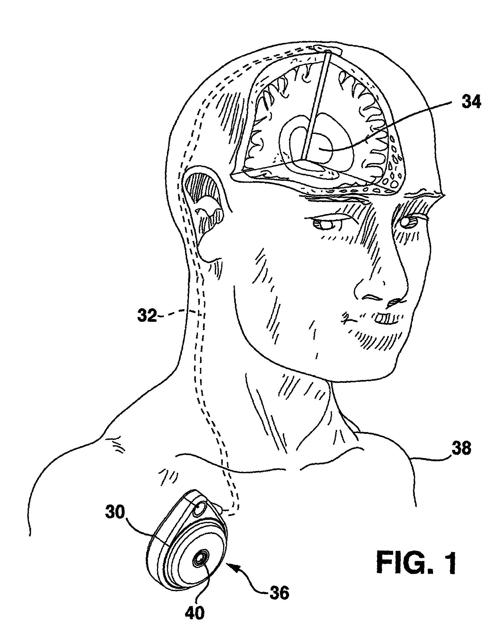
[0023]FIG. 1 shows the environment of an implantable medical device known as an implantable therapeutic substance delivery device 30, also known as a drug pump, having a peristaltic pump with optimized peristaltic pump motor drive embodiment. The therapeutic substance delivery device 30 operates to infuse a therapeutic substance 36 stored in therapeutic substance reservoir 44 at a programmed flow rate into a patient 38. The therapeutic substance delivery device 30 can be used for a wide variety of therapies such as pain, spasticity, cancer, and many other medical conditions.

[0024]The implantable therapeutic substance delivery device 30 is typically implanted by a surgeon in a sterile surgical procedure performed under local, regional, or general anesthesia Before implanting the therapeutic substance delivery device 30, a catheter 32 is typically implanted with the distal end position at the desired therapeutic substance delivery site 34 and the proximal end tunneled to the location ...


PUM


Abstract

A medical device known as an implantable therapeutic substance delivery device is configured for implanting in humans to deliver a therapeutic substance such as pharmaceutical compositions, genetic materials, and biologics to treat a variety of medical conditions such as pain, spasticity, cancer, and many other conditions. The infusion device incorporates a stepper motor that controls the infusion flow rate during the service life of the device. The stepper motor is controlled by continuously varying electrical pulse parameters based on the continuously decreasing power source voltage during the service life of the substance delivery device. In particular the stepper motor electrical pulse parameters, especially duty cycle, are selected to efficiently compensate for decreasing battery voltage thereby optimizing the motor performance while maximizing the power source service life. The infusion device has a housing, a power source, a therapeutic substance reservoir, a therapeutic substance pump, and electronics. Many embodiments of the therapeutic substance delivery device with optimized pump motor drive and its methods of operation are possible.

Description

RELATED APPLICATIONS[0001]This application is related to the following co-pending applications entitled “Implantable Therapeutic Substance Infusion Device With Motor Stall Detector” by inventors Seifert et al. and “Implantable Therapeutic Substance Infusion Device With Active Longevity Projection” by inventors Rogers et al. Ser. No. 09 / 809,809 Filed Mar. 16, 2001, which are not admitted as prior art with respect to the present invention by its mention in this cross reference section.FIELD OF THE INVENTION[0002]This disclosure relates to a medical device and more particularly to an implantable therapeutic substance infusion device, also known as an implantable drug pump, optimized peristaltic pump motor drive circuit.BACKGROUND OF THE INVENTION[0003]The medical device industry produces a wide variety of electronic and mechanical devices for treating patient medical conditions. Depending upon medical condition, medical devices can be surgically implanted or connected externally to the...

Claims


Application Information

Patent Timeline
Patent Type & Authority Patents(United States)
IPC IPC(8): A61K9/22A61M5/142A61M5/172H02P8/16
CPCA61M5/14276A61M5/172H02P8/16A61M2205/8212
Inventor ROGERS, CHARLES R.SEIFERT, GEORGE P.
Owner MEDTRONIC INC
Why Eureka
Try Eureka