DC motor rotation information detecting device

a technology of detecting device and information, which is applied in the direction of dynamo-electric converter control, dc motor rotation control, motor/generator/converter stopper, etc., can solve the problems of increasing the cost of sensors and sensor mounting, increasing the number of signal lines, and reducing reliability, so as to increase the signal strength, accurately detect, and increase the impedance

Inactive Publication Date: 2006-10-17
DENSO CORP
View PDF57 Cites 30 Cited by
  • Summary
  • Abstract
  • Description
  • Claims
  • Application Information

AI Technical Summary

Benefits of technology

[0012]The present invention has an object to provide a DC motor rotation information detecting device that can accurately detect rotation information of the motor even in applications in which start and stop of the motor are frequently repeated.
[0014]In the period from when a motor to detect rotation information from starts braking operation to when it stops, even when the motor is in a state immediately before it stops, that is, an induction current due to power generation operation flows little through it as the speed of inertial rotation decreases, a current equal to or greater than the reference current value flows through the motor (motor coil). As a result, signal strength corresponding to the reference current value is surely obtained for a surge component waveform superimposed on a signal waveform of at least one of a current flowing through the motor and a voltage between the terminals of the motor. Accordingly, the surge detection errors (count errors) attributable to reduction in current values are reduced. In this way, by adopting the construction as a device for detecting rotation information of a DC motor, rotation information of the motor can be accurately detected even in applications in which start and stop of the motor are frequently repeated.
[0017]Increasing impedance between the terminals of a motor to detect rotation information increases signal strength for a surge component waveform superimposed on a signal waveform of a voltage between the terminals (voltage waveform between the terminals) of the motor and reveals it. Accordingly, by providing the section in which impedance between the terminals of the motor is increased, as detection regions of a surge component waveform superimposed on the signal waveform, the surge detection errors (count errors) attributable to decrease in current values are suitably reduced, and rotation information of the motor can be accurately detected even in applications in which start and stop are frequently repeated.

Problems solved by technology

However, since such methods require sensors such as the Hall sensors and potentiometers, an increase in costs of the sensors and sensor mounting, and reduction in reliability due to spatial limitations, an increase in the number of signal lines, and sensor life cannot be ignored.
However, since the induction current decreases as the rotation speed of the motor M decreases, a surge detection error (counting error) E or the like might occur immediately before the motor stops (timing T12).
Furthermore, such detection errors are accumulated in applications in which start and stop of the motor are frequently repeated, possibly leading to a large detection error.

Method used


Image

  • DC motor rotation information detecting device
  • DC motor rotation information detecting device
  • DC motor rotation information detecting device

Examples


Embodiment Construction

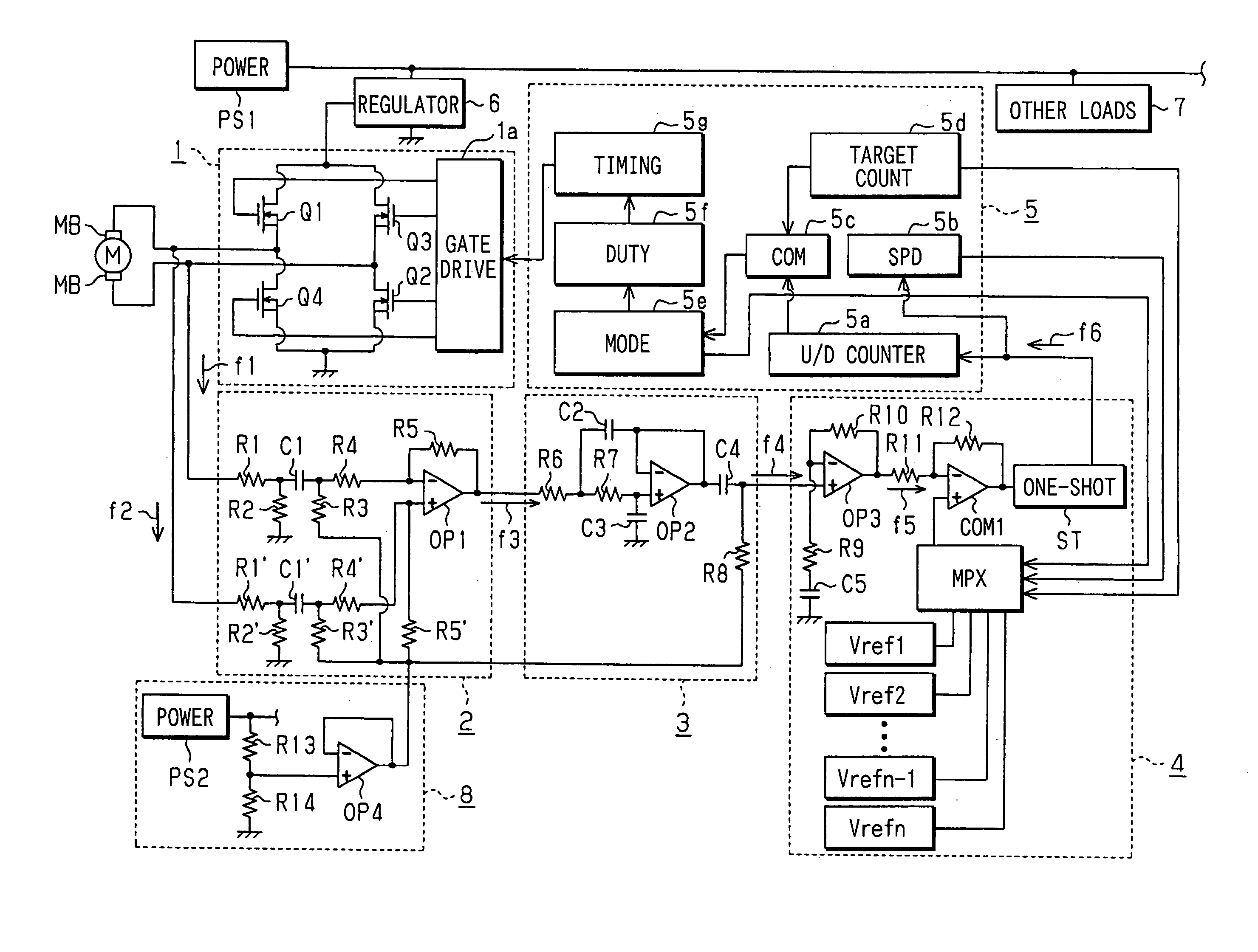
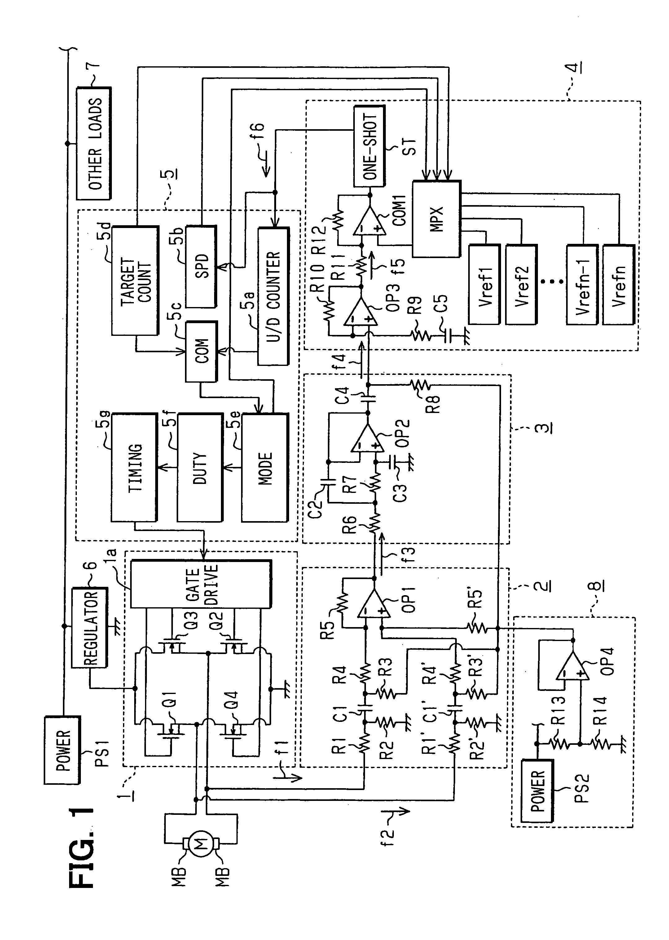
[0028]As shown in FIG. 1, a DC motor rotation information detecting device primarily comprises a driving current control circuit 1, a driving waveform detection circuit 2, a rotation signal extraction circuit 3, a rotation pulse generation circuit 4, a control circuit 5, and a voltage regulator 6. The device is connected with a power supply PS1 of, e.g., power voltage 12V.

[0029]A DC motor M, rotation information of which is to be detected, has a pair of brushes MB connected with a driving current control circuit 1 that controls a driving current to the motor M, and a driving waveform detection circuit 2 for detecting a voltage waveform between the terminals of the motor M.

[0030]The driving current control circuit 1 includes four power MOSFETs (field effect transistor) Q1 to Q4 as switching elements. A rotation direction, rotation speed, and the like of the motor M are controlled by pulse width modulation (PWM) control through a bridge circuit (full bridge) comprising the transistors...


PUM


Abstract

A rotation information detection device detects rotation information of a DC motor based on a surge component waveform superimposed on a voltage waveform between the terminals of the DC motor or a current waveform of the DC motor, a circuit is provided which supplies a current of a current value Ipwm 45% during motor forward rotation or Ipwm 55% during reverse motor rotation to the motor over the period from when the motor starts braking operation to when it stops.

Description

CROSS REFERENCE TO RELATED APPLICATION[0001]This application is based on and incorporates herein by reference Japanese Patent Application No. 2004-216453 filed on Jul. 23, 2004.FIELD OF THE INVENTION[0002]The present invention relates to a DC motor rotation information detecting device, and more particularly to a device that detects rotation information of a DC motor having brushes based on a signal waveform such as its current waveform and a voltage waveform between its terminals.BACKGROUND OF THE INVENTION[0003]An automobile includes a number of systems using DC brush motors, for comfort and usability. For example, an air conditioner is provided with several DC motors for driving a door for changing its outlet and an air mix amount. The positions of door mirrors, sheet positions, and window positions in a power window system are operated by DC motors used as actuators. Furthermore, DC motors are also used in a system that changes the optical axis of headlight according to a steeri...

Claims


Application Information

Patent Timeline
Patent Type & Authority Patents(United States)
IPC IPC(8): H02P6/08H02P7/06
CPCH02P7/0044Y10S388/909H02P7/0094H02P7/04
Inventor SASAYA, TAKANARITAKAHASHI, MICHIRU
Owner DENSO CORP
Why Eureka
Try Eureka