Impact driver having an external mechanism which operation mode can be selectively switched between impact and drill modes

a technology of impact driver and external mechanism, which is applied in the direction of percussive tools, portable drilling machines, manufacturing tools, etc., can solve the problems of reducing usability, affecting the operation of the operating handle, and affecting the operation of the engaging pin and the operating handle, so as to improve the operability and prevent the enlargement of the housing. , the effect of simple structur

Active Publication Date: 2006-10-24
MAKITA CORP
View PDF19 Cites 115 Cited by
  • Summary
  • Abstract
  • Description
  • Claims
  • Application Information

AI Technical Summary

Benefits of technology

[0008]In order to solve this problem, an object of the present invention is to provide an impact driver in which selection of a drill mode is feasible with a simpler structure and a usability is excellent.
[0012]According to the first aspect of the present invention, both boring and screwing can be conducted with an impact driver only, whereby improvement of its operability can be expected. In particular, the impact driver has a simple structure in which the connection status between the hammer and the anvil is switched using the connection member. Therefore, a drill mode is obtained without fail and enlargement of the housing is prevented, and the drill mode is feasible with a low cost. Moreover, when the connecting member engages with the hammer at the first slide position to select an impact mode, the hammer which is connected with the connecting member engages with the anvil, whereby the mass of the hammer itself which moves back and forth can be set to be smaller. As a result, vibration can be reduced in the impact mode, thereby maintaining excellent operability.
[0014]According to the third aspect of the present invention, in addition to the effect of the first aspect, the connecting member can be simply formed and can engage with or disengage from the anvil smoothly, thereby obtaining excellent operability.

Problems solved by technology

Consequently, it is troublesome to exchange tools and therefore usability might be reduced.
Consequently, the engaging pin and the operating handle suffer from a heavy burden.
As a result, when a load on the anvil increases the hammer might move backward to generate impact or the engaging pin might be broken, which deteriorates reliability.
Moreover, in Japanese Patent No. 3372345, a housing has to be extended in the axial direction in order to space a stroke of movement, and further the structure might be complex.
As a result, operability might be lowered due to difficulty in downsizing or cost might be higher.

Method used


Image

  • Impact driver having an external mechanism which operation mode can be selectively switched between impact and drill modes
  • Impact driver having an external mechanism which operation mode can be selectively switched between impact and drill modes
  • Impact driver having an external mechanism which operation mode can be selectively switched between impact and drill modes

Examples


first embodiment

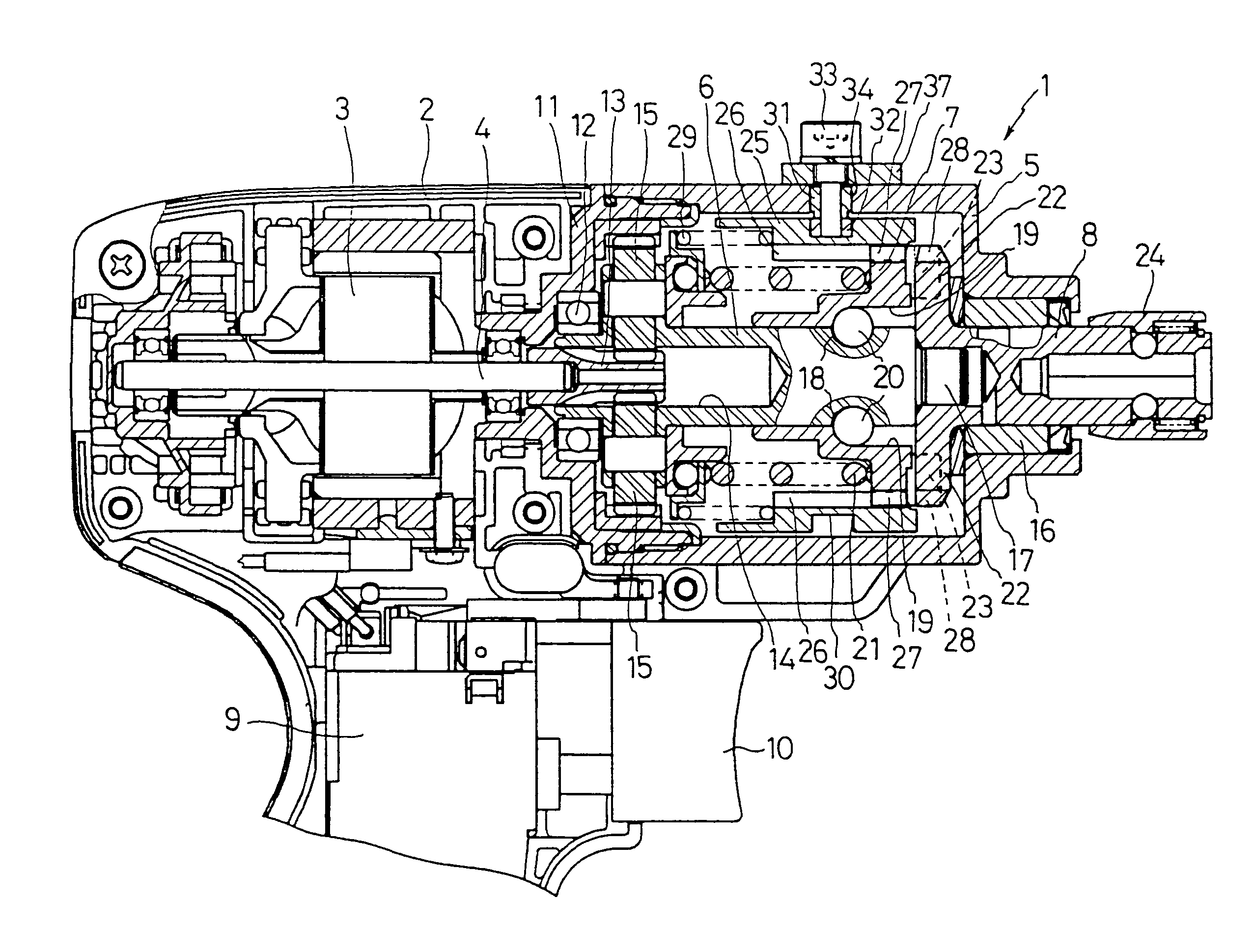
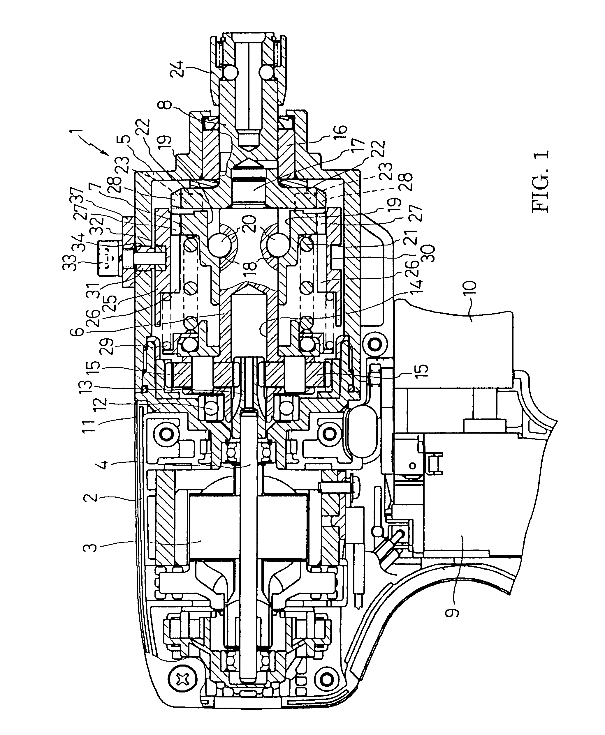
[0034]FIG. 1 is a partial vertical section view showing an example of an impact driver. An impact driver 1 has a motor 3 accommodated in a body housing 2. At the front of the body housing 2, a hammer case 5 accommodating a spindle 6 and a hammer 7 is incorporated as a front housing. An anvil 8 protrudes at the front of the hammer case 5. The reference number 9 denotes a switch and the reference number 10 denotes a trigger. Between the body housing 2 and the hammer case 5, a gear housing 11 is provided which axially supports a motor shaft 4 of the motor 3 so as to allow the motor shaft 4 to protrude into the hammer case 5. Moreover, the gear housing 11 axially supports the end of the spindle 6 through a ball bearing 12. A pinion 13 is mounted at the top of the motor shaft 4 which is inserted coaxially with play into a hollow portion 14 formed at the end of the spindle 6. In accordance with this structure, the motor shaft 4 engages with a plurality of planetary gears 15, 15 . . . whic...

second embodiment

[0047]Next, another embodiment of the present invention will be explained.

[0048]As shown in FIG. 5, an impact driver has a motor 3 accommodated at the rear of a body housing 2 formed of a pair of right and left half-housings. In front of the motor 3, a planetary gear reduction mechanism 5 with a clutch mechanism, an impact mechanism 6 and a percussion mechanism 7 are respectively provided, and an anvil 8 coaxially provided with a motor shaft 4 of the motor 3 is protruding at the front end. The reference number 9 denotes a switch of a driving circuit of the motor 3, and the reference number 10 denotes a trigger for turning ON the switch 9 when the trigger is pressed.

[0049]As shown in FIGS. 6 and 7, the planetary gear reduction mechanism 5 is housed between a cylindrical motor bracket 11 and a gear case 12. The motor bracket 11 is fixed in the body housing 2 and axially supports the motor shaft 4. The gear case 12 is connected in front of the motor bracket 11 and formed in a cylindric...


PUM

PropertyMeasurementUnit
torqueaaaaaaaaaa
diameteraaaaaaaaaa
outer circumferenceaaaaaaaaaa

Abstract

An impact driver in which a drill mode can be selected without fail is provided. In a hammer case, a connecting sleeve is provided so as to be slidable back and forth. At the backward position, the connecting sleeve engages with only a first engaging tooth provided on the outer circumference of the hammer for rotating integrally. At the forward position, it engages with both the first engaging tooth of the hammer and a second engaging tooth of an anvil for rotating integrally with both of them, and thus a drill mode is obtained. Further, an operating bolt is provided in the hammer case to be inserted into a concave groove of the connecting sleeve through a guide groove formed in the hammer case. The operating bolt slides the connecting sleeve to the forward or backward position by its movement in the guide groove.

Description

BACKGROUND OF THE INVENTION[0001]This application claims the benefit of Japanese Patent Application Number 2004-68046 filed Mar. 10, 2004 and Japanese Patent Application Number 2004-349000 filed Dec. 1, 2004, the entirety of which is incorporated by reference.1. FIELD OF THE INVENTION[0002]The present invention relates to an impact driver capable of applying rotation and the intermittent impact operation to an anvil protruding to the front of a housing.2. DESCRIPTION OF THE RELATED ART[0003]An impact driver has a well-known structure in which a spindle rotated by a motor is connected with a hammer through cam grooves and balls, and an anvil which is locked in the rotative direction is axially provided in front of the hammer, whereby rotation of the spindle is transferred to the anvil through the hammer. With this structure, when a load on the anvil exceeds a predetermined value, the hammer moves backward along the cam grooves to temporarily disengage from the anvil, and thereafter i...

Claims


Application Information

Patent Timeline
Patent Type & Authority Patents(United States)
IPC IPC(8): B25D15/02B25B21/00B25B21/02B25D9/00
CPCB25B21/00B25B21/026
Inventor FURUTA, TAKEFUMIITO, YOSHIHIRO
Owner MAKITA CORP
Why Eureka
Try Eureka