Apparatus and method for abrading a workpiece

Inactive Publication Date: 2006-10-24
NOVELLUS SYSTEMS
View PDF14 Cites 40 Cited by
  • Summary
  • Abstract
  • Description
  • Claims
  • Application Information

AI Technical Summary

Benefits of technology

[0007]According to an aspect of the invention there is provided an apparatus for abrading a workpiece that comprises a first plate assembly having a first surface for supporting the workpiece and a second plate assembly having a second surface for engaging the workpiece to abrade a portion thereof. A displacement shaft is mounted for movement with

Problems solved by technology

This can result in a loss of rigidity and control during the abrading cycle, which in turn may result in reduced accuracy.
In addition, machines of this type oftentimes utilize only a single cylinder to apply pressure from above during the abrading cycle.
In some cases, however, the single cylinder configurations do not apply sufficient pressure for certain abrading processes.
Such arrangements, however, may have a problem associated with sealing gaskets and the creation of unwanted budding effects in the system during the lapping cycle.
While effective for precision abrading, the apparatus is subject to an undesired cantilever effect during the abrading cycle.
That is, when pressure is exerted during the lapping cycle, the arm and the column tend to act as a cantilever which results in loss of rigidit

Method used


Image

  • Apparatus and method for abrading a workpiece
  • Apparatus and method for abrading a workpiece
  • Apparatus and method for abrading a workpiece

Examples


Embodiment Construction

[0013]The following detailed description of the invention is merely exemplary in nature and is not intended to limit the invention or the application and uses of the invention. Furthermore, there is no intention to be bound by any theory presented in the preceding background of the invention or the following detailed description of the invention.

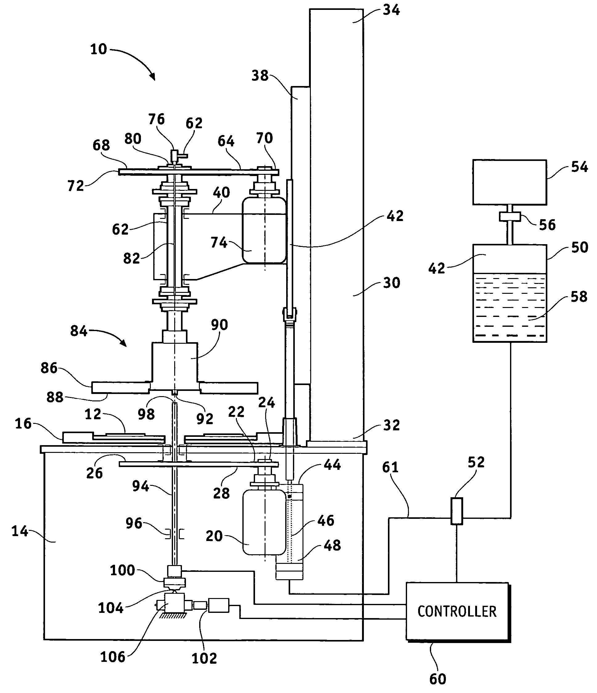
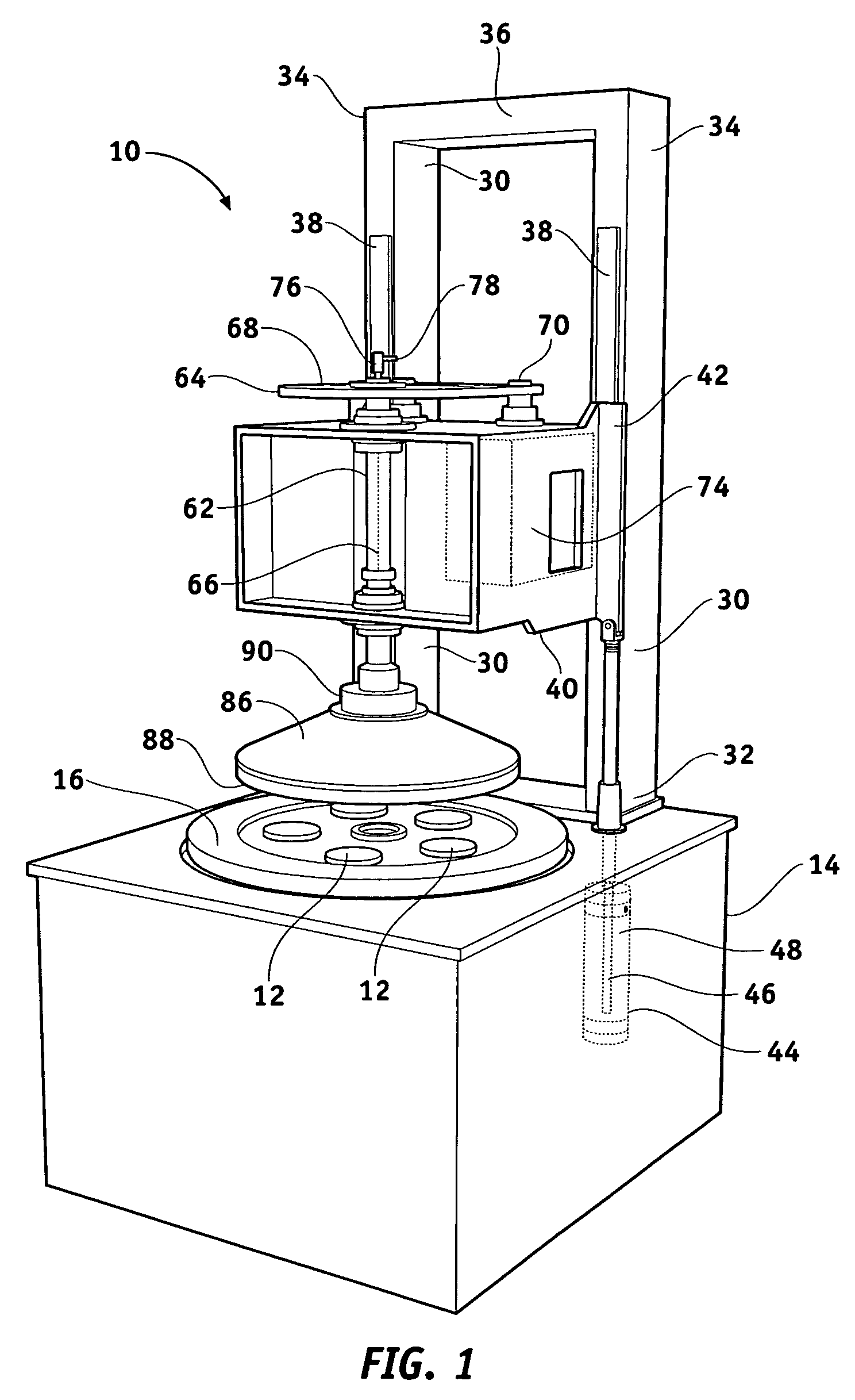
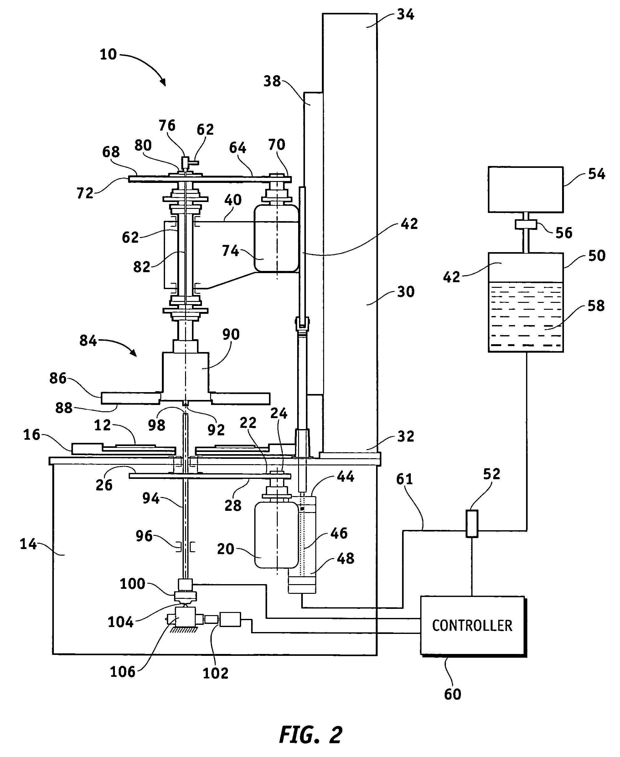
[0014]FIG. 1 is an isometric view of an abrading apparatus in accordance with the first embodiment of the present invention. Apparatus 10 is capable of abrading any suitable workpiece 12 which may be made of metal, ceramic, semiconductor material (e.g. silicon), or any other abradable material. As used herein, the term “abrading” is intended to include grinding, polishing, planarizing, finishing, and / or lapping and the like. In accordance with one explempary embodiment of the present invention, abrading apparatus 10 comprises a base 14 including a lower abrading wheel 16. Lower abrading wheel 16 is coupled to a motor 20 (FIG. 2) which serves...


PUM

PropertyMeasurementUnit
Thicknessaaaaaaaaaa
Currentaaaaaaaaaa
Displacementaaaaaaaaaa

Abstract

An apparatus for abrading a workpiece comprises a first plate assembly having a first surface for supporting a workpiece and a second plate assembly having a second surface for engaging the workpiece to abrade a portion thereof. A displacement shaft is mounted for movement with respect to the upper and lower plate assemblies and has a first end configured to engage the upper plate assembly. A feedback assembly is coupled to the displacement shaft for moving the displacement shaft to substantially maintain a predetermined load exerted on the displacement shaft by the upper plate assembly.

Description

CROSS-REFERENCES TO RELATED APPLICATIONS[0001]This application claims the benefit of U.S. Provisional Application No. 60 / 450,242, filed Feb. 25, 2003.FIELD OF THE INVENTION[0002]This invention relates generally to a method and apparatus for abrading the workpiece, and more particularly, to the abrading or grinding of workpieces using an abrading apparatus that provides automatic thickness control (ATC) through the use of a stepper motor and pressure sensor.BACKGROUND OF THE INVENTION[0003]Precision abrading machines are well known and are often utilized to abrade one or more surfaces of a workpiece to achieve a desired dimension. This is generally accomplished by using a process known as lapping which removes small, controlled amounts of material from the workpiece surface. One variety of abrading machine employs a fixed bridge. The bridge supports an upper lapping plate that is configured for rotation and vertical movement between a lower abrading position and an upper loading and ...

Claims


Application Information

Patent Timeline
IPC IPC(8): B24B51/00B24B7/00B24B7/06B24B37/08B24B49/02B24B49/16B24B55/02
CPCB24B7/06B24B37/08B24B49/02B24B49/16B24B55/02
Inventor ZELENSKI, ALEKSANDERCHEPRASOV, SERGEY
Owner NOVELLUS SYSTEMS
Why Eureka
Try Eureka