Methods and apparatus for pitch control power conversion

a technology of pitch control and power conversion, applied in the direction of electric generator control, dynamo-electric converter control, machines/engines, etc., can solve the problems of not being believed to have been addressed and the need to absorb regenerative energy continuously new

Active Publication Date: 2006-10-24
GE INFRASTRUCTURE TECH INT LLC
View PDF19 Cites 98 Cited by
  • Summary
  • Abstract
  • Description
  • Claims
  • Application Information

AI Technical Summary

Benefits of technology

[0009]It will thus be apparent that various configurations of the present invention realize advantages in system cost, reliability and / or availability, particularly when used in wind turbine pitch control systems. In addition, some configurations of the present invention used in wind turbine pitch control systems can be configured to advantageously provide energy swapping between pitch motor drive systems on a single DC bus and / or provide other ways to dissipate regenerative energy in single pitch motor drive systems and / or advantageously allow energy swapping between pitch control power converters. Energy swapping during operation poses advantages over single converter operation by allowing a reduction or minimization of the number and rating of dynamic brake (DB) resistors and DC link capacitors.

Problems solved by technology

The requirement to absorb regenerative energy continuously is new and is not believed to have been addressed by previously known wind turbine pitch system configurations.

Method used


Image

  • Methods and apparatus for pitch control power conversion
  • Methods and apparatus for pitch control power conversion
  • Methods and apparatus for pitch control power conversion

Examples


Embodiment Construction

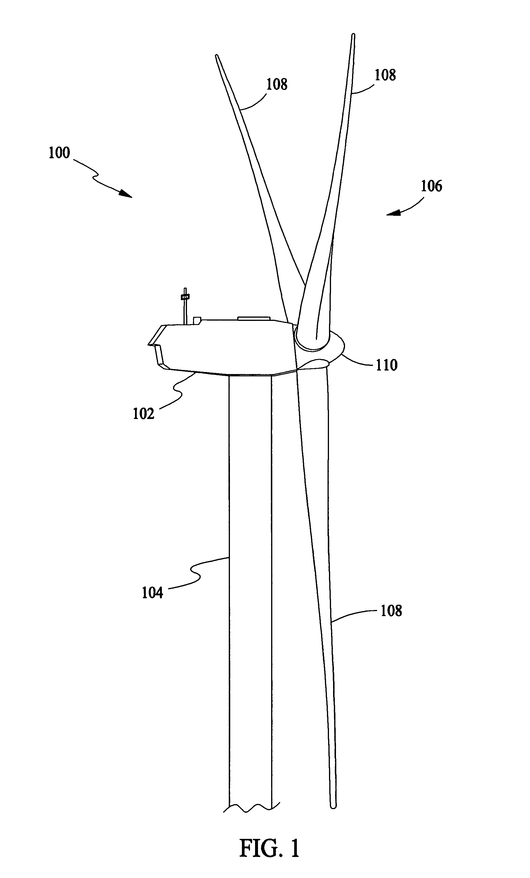
[0018]In some configurations and referring to FIG. 1, a wind turbine 100 in some configurations comprises a nacelle 102 housing a generator (not shown in FIG. 1). Nacelle 102 is mounted atop a tall tower 104, only a portion of which is shown in FIG. 1. Wind turbine 100 also comprises a rotor 106 that includes a plurality of rotor blades 108 attached to a rotating hub 110. Although wind turbine 100 illustrated in FIG. 1 includes three rotor blades 108, there are no specific limits on the number of rotor blades 108 required by the present invention.

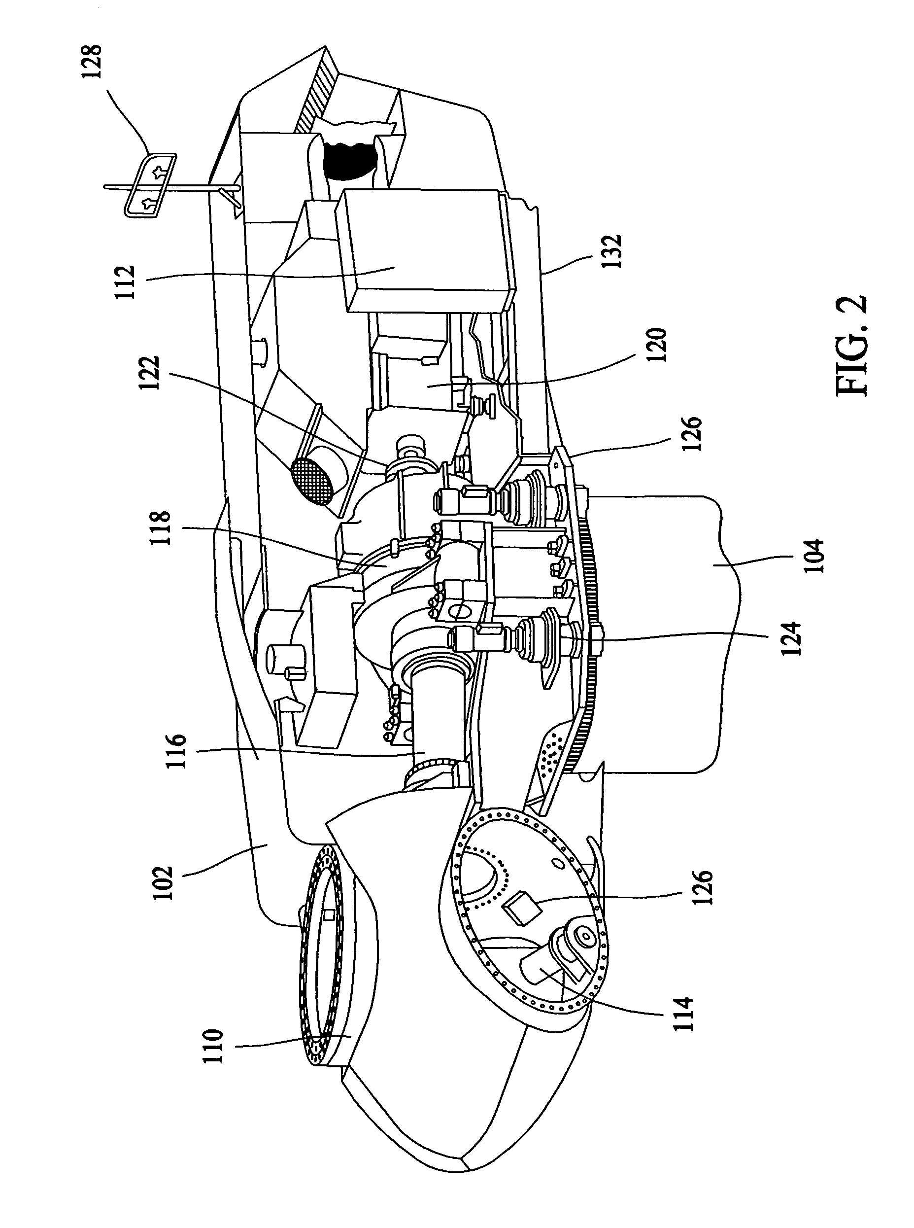
[0019]In some configurations and referring to FIG. 2, various components are housed in nacelle 102 atop tower 104 of wind turbine 100. The height of tower 104 is selected based upon factors and conditions known in the art. In some configurations, one or more microcontrollers within control panel 112 comprise a control system are used for overall system monitoring and control including pitch and speed regulation, high-speed shaft and yaw bra...


PUM


Abstract

A method for powering a pitch motor drive system for at least one DC pitch motor of a wind turbine includes rectifying a voltage using a bridge circuit to thereby supply a DC link voltage to a bridge comprising active switching devices, and utilizing at least one link capacitor to smooth the DC link voltage and act as an energy sink and source for the DC pitch motor or motors.

Description

BACKGROUND OF THE INVENTION[0001]This invention relates generally to control of DC motors, and more particularly to methods and apparatus that are particularly useful for efficiently controlling DC pitch motors in wind turbines.[0002]Recently, wind turbines have received increased attention as an environmentally safe and relatively inexpensive alternative energy source. With this growing interest, considerable efforts have been made to develop wind turbines that are reliable and efficient.[0003]Generally, a wind turbine includes a rotor having multiple blades. The rotor is mounted on a housing or nacelle, which is positioned on top of a truss or tubular tower. Utility grade wind turbines (i.e., wind turbines designed to provide electrical power to a utility grid) can have large rotors (e.g., 30 or more meters in diameter). Blades on these rotors transform wind energy into a rotational torque or force that drives one or more generators, rotationally coupled to the rotor through a gea...

Claims


Application Information

Patent Timeline
Patent Type & Authority Patents(United States)
IPC IPC(8): H02P7/00
CPCF03D7/0224F05B2260/76Y02E10/726Y02E10/723Y02E10/721Y02E10/72
Inventor HARBOURT, CYRUS DAVIDMELIUS, JEFFREY ALANRIDENOUR, AMY MARLENEWANNER, JR., DAVID GERARDEDMUNDS, HOWARD ROSSWILKINSON, ANDREW SCOTT
Owner GE INFRASTRUCTURE TECH INT LLC
Why Eureka
Try Eureka