Asymmetrical AMR wheatstone bridge layout for position sensor

a position sensor and asymmetrical technology, applied in the field of position sensors, to achieve the effect of improving performan

Active Publication Date: 2006-10-24
HONEYWELL INT INC
View PDF11 Cites 58 Cited by
  • Summary
  • Abstract
  • Description
  • Claims
  • Application Information

AI Technical Summary

Benefits of technology

[0015]The asymmetrically arranged magnetoresistive bridge components generally comprise an asymmetrical magnetoresistive bridge circuit based on a first set of magnetoresistors asymmetrically offset from a second set of magnetoresistors. The first and second sets of magnetoresistors are configured upon a substrate upon which the integrated circuit is formed. In general, the one set of magnetoresistors comprises a different pattern of magnetoresistors than the other set of magnetoresistors. An improved performance can thus be obtained from the magnetoresistive bridge circuit utilizing such an asymmetrical bridge layout, where the two halves of the circuit are not mirror images of one another. It is important to note, however, that it is not the number of magnetoresistors alone that are utilized to provide asymmetry. For example, the two halves described above can possess the same number of magnetoresistors, but can possess varying spacing between runners thereof.

Problems solved by technology

One of the problems with such magnetic detection devices, such as the sensors described above, is that such devices, while adequate for some sensing applications, are typically configured in a symmetrical arrangement of magnetic sensing components, however an asymmetric configuration can often provide enhanced performance.

Method used


Image

  • Asymmetrical AMR wheatstone bridge layout for position sensor
  • Asymmetrical AMR wheatstone bridge layout for position sensor
  • Asymmetrical AMR wheatstone bridge layout for position sensor

Examples


Embodiment Construction

[0027]The particular values and configurations discussed in these non-limiting examples can be varied and are cited merely to illustrate at least one embodiment and are not intended to limit the scope thereof.

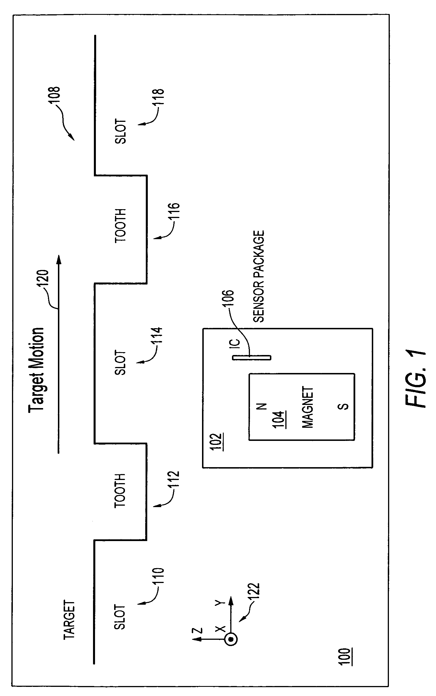
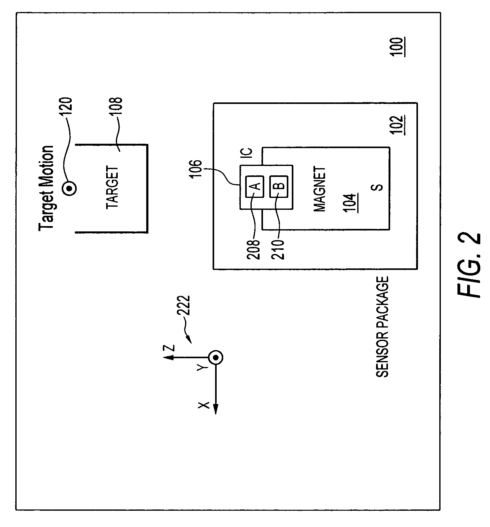
[0028]FIG. 1 illustrates an X-axis view of a magnetic sensing system 100, which can be implemented in accordance with an embodiment. Similarly, FIG. 2 illustrates a Y-axis view of the magnetic sensing system 100 depicted in FIG. 1 in accordance with an embodiment. Note that in FIGS. 1–6, identical or similar parts or components are generally indicated by identical reference numerals. Thus, FIGS. 1–6 can be interpreted together in order to describe one or more embodiments.

[0029]Magnetic sensing system 100 generally includes a magnet 104 and an integrated circuit (IC) 106 disposed within a sensor package 102. The magnet 104 is generally located proximate to a target 108 that includes a plurality of teeth 112, 116 and a plurality of slots 110, 114, and 118 formed therebetween. The...


PUM


Abstract

A magnetic sensor includes a magnet located proximate to a target comprising a plurality of teeth and a plurality of slots formed therebetween. An integrated circuit is generally located on one side of the magnet wherein the integrated circuit comprises a plurality of asymmetrically arranged magnetoresistive bridge components, wherein the integrated circuit and the magnet are configured into a sensor package, such that the plurality of asymmetrically arranged magnetoresistive bridge components enables a detection of at least one tooth among the plurality of target teeth.

Description

TECHNICAL FIELD[0001]Embodiments are generally related to position sensors. Embodiments are also related to magnetic sensors and magnetic sensing components. Embodiments additionally are related to magnetoresistive and Hall Effect sensors.BACKGROUND OF THE INVENTION[0002]Magnetic sensors typically rely upon permanent magnets to detect the presence or absence of a magnetically permeable object within a certain predefined detection zone relative to the sensor. In combination with the permanent magnet, some sensors of this type utilize Hall Effect and / or magnetoresistive components located at particular positions relative to the permanent magnet and other. Magnetoresistive elements, for example, can be disposed at symmetrical positions relative to the permanent magnet in order to implement magnetic sensing operations.[0003]Proximity sensors of this type, whether they use Hall effect elements or magnetoresistive elements, can be configured to sense the presence or absence of a magnetica...

Claims


Application Information

Patent Timeline
Patent Type & Authority Patents(United States)
IPC IPC(8): G01B7/30G01B7/14
CPCG01D5/147G01D5/16G01D5/00
Inventor BUSCH, NICHOLAS F.
Owner HONEYWELL INT INC
Why Eureka
Try Eureka