Supercharger

a supercharger and centrifugal technology, applied in the direction of electric generator control, piston pump, fluid coupling, etc., can solve the problems of difficult manufacturing of the very precise bores of the case components, the difficulty of machining, measuring and matching procedures, and the difficulty of manufacturing the assembly of the case components. to achieve the effect of convenient manufacturing and servi

Inactive Publication Date: 2006-10-31
VORTECH ENG
View PDF59 Cites 20 Cited by
  • Summary
  • Abstract
  • Description
  • Claims
  • Application Information

AI Technical Summary

Benefits of technology

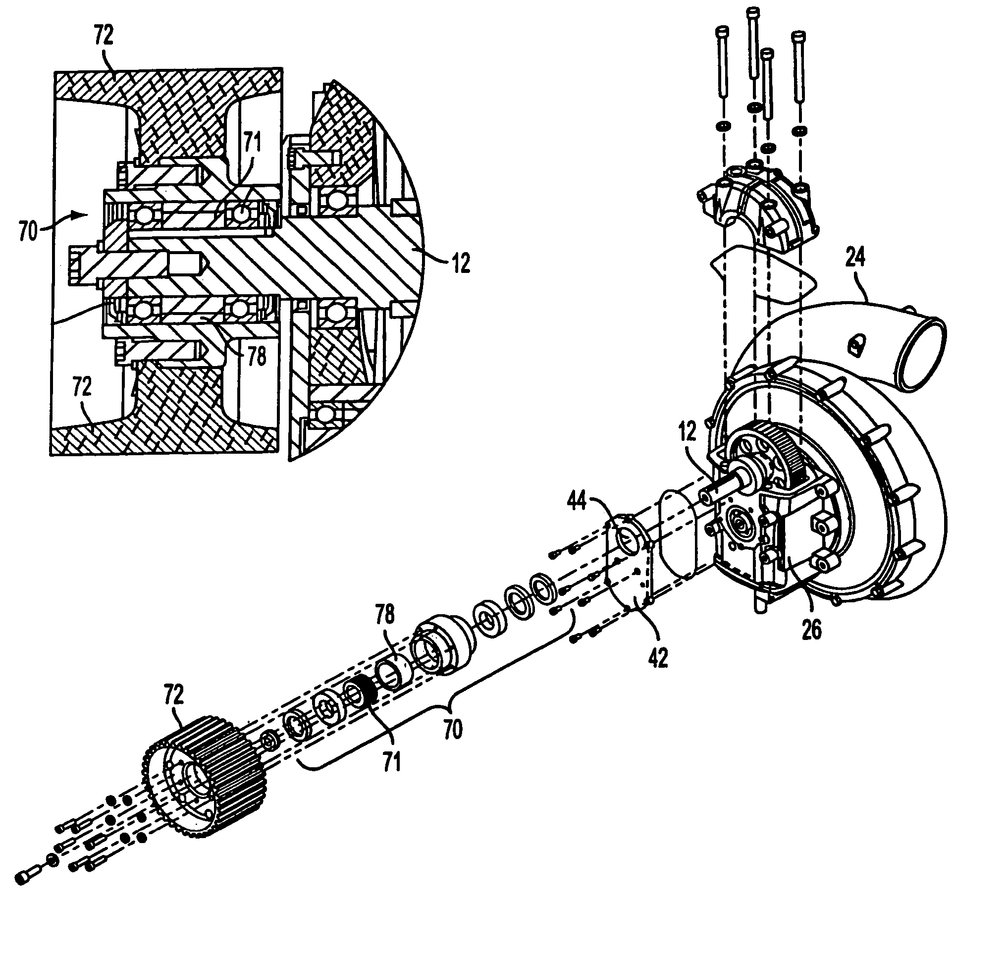
[0005]The present invention provides a very efficient supercharger that is easy to manufacture and service.
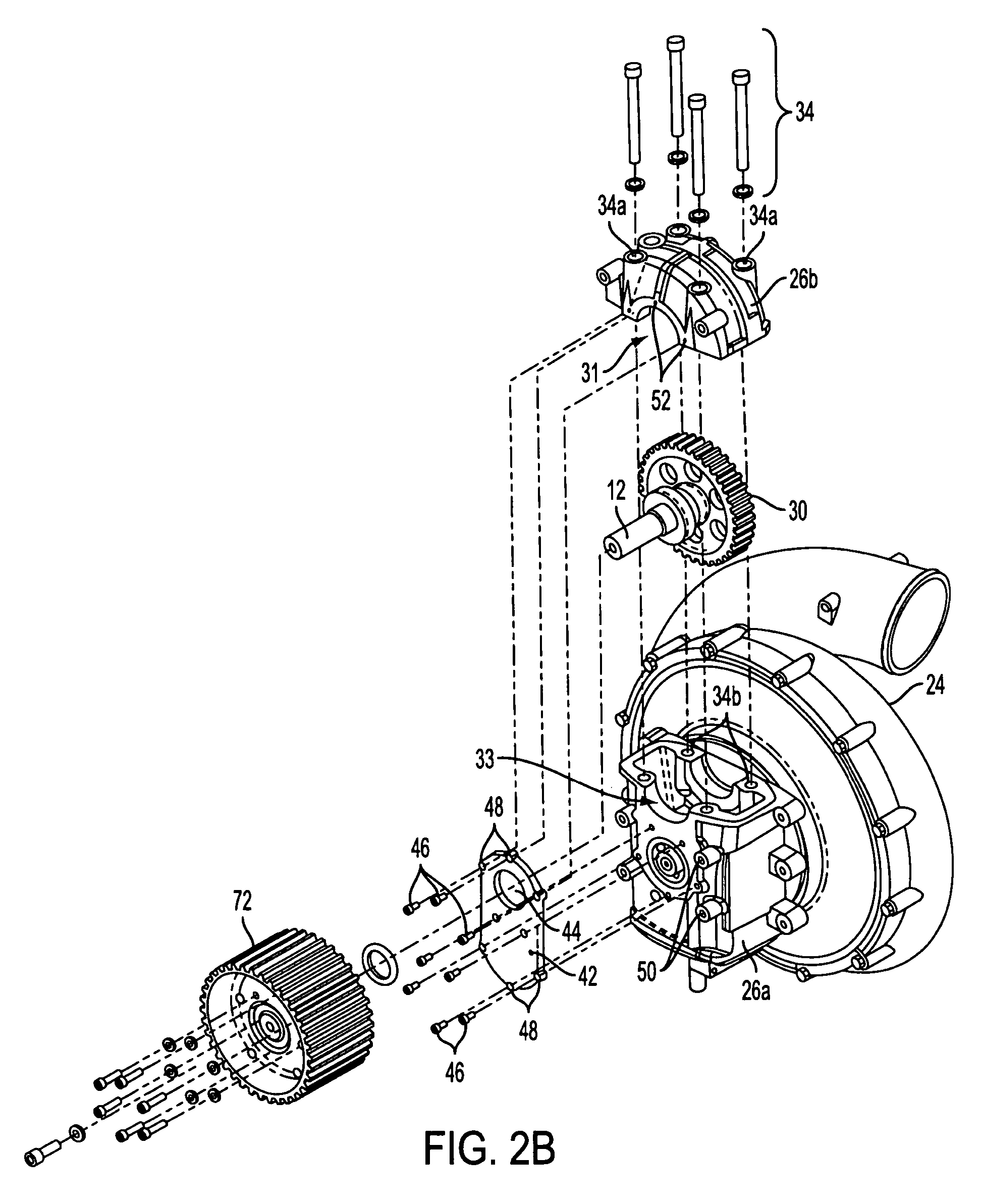
[0006]One feature of the present invention comprises a supercharger that has a case, or housing that is split into a primary section and a removable section. This two-piece housing greatly enhances and simplifies the ability to attain the required precision manufacturing tolerances.
[0009]A further feature of the present invention comprises an impeller shaft support designed to reduce mechanical stress and associated rotordynamic instabilities.

Problems solved by technology

A significant problem exists in manufacturing the very precise bores of the case components.
These extremely tight tolerances challenge the capabilities of even the newest and best state-of-the-art computer-controlled machining centers.
Manufacturing these assemblies requires expensive and time-consuming set-up, machining, measuring and matching procedures.
Even with very careful manufacturing procedures, a significant component rejection rate exists, due to parts that do not meet the strict tolerance requirements.

Method used


Image

  • Supercharger
  • Supercharger
  • Supercharger

Examples


Embodiment Construction

[0026]In the following paragraphs, the present invention will be described in detail by way of example with reference to the attached drawings. Throughout this description, the preferred embodiment and examples shown should be considered as exemplars, rather than as limitations on the present invention. As used herein, the “present invention” refers to any one of the embodiments of the invention described herein, and any equivalents. Furthermore, reference to various feature(s) of the “present invention” throughout this document does not mean that all claimed embodiments or methods must include the referenced feature(s).

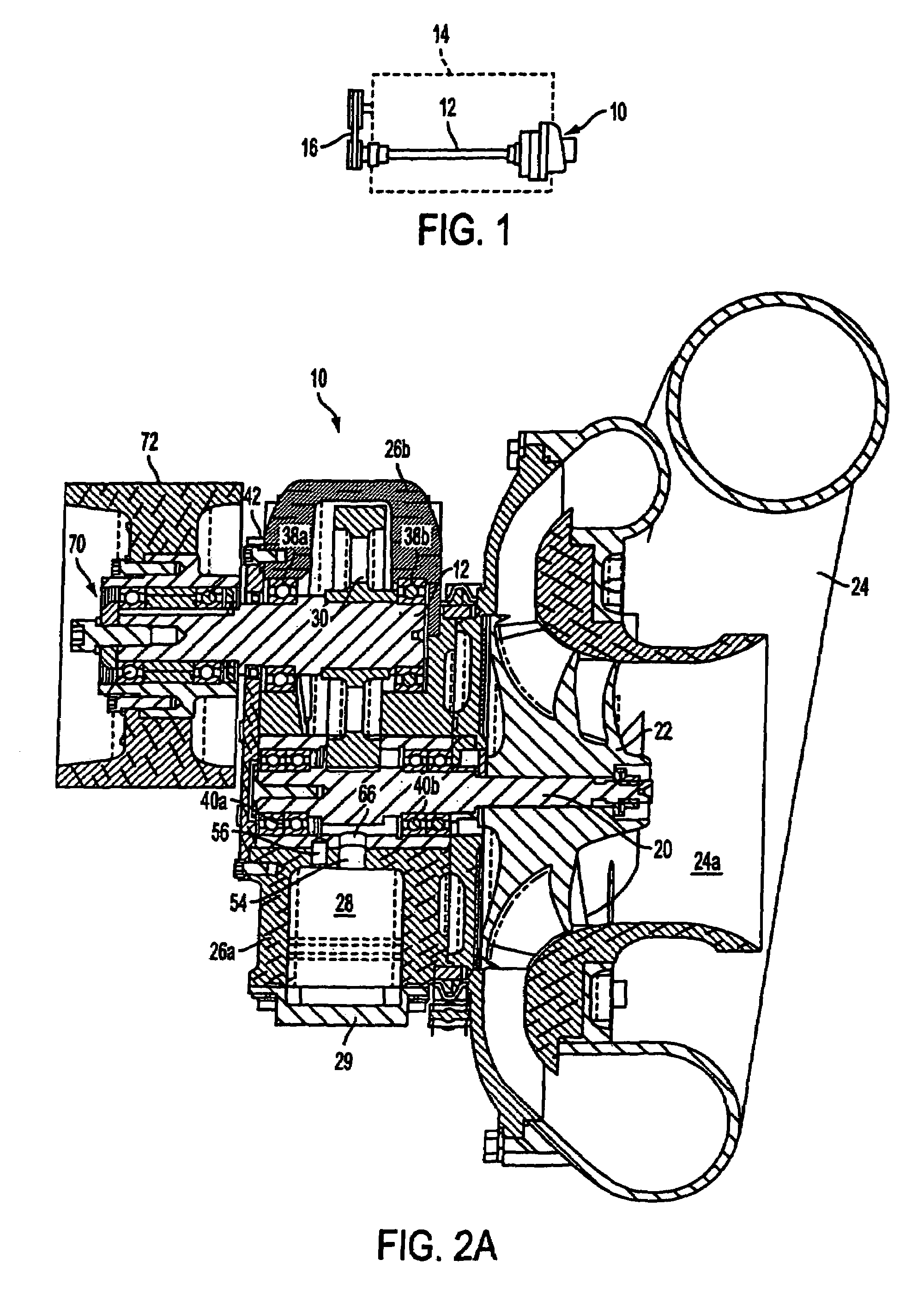
[0027]Referring to FIG. 1, a supercharger 10 constructed according to the present invention includes a driveshaft 12 for receiving rotational force from an engine 14 via a pulley and belt assembly 16. More particularly, one end of the driveshaft 12 is attached to supercharger 10 and the opposite end is attached to the pulley and belt assembly 16. In the illustrated e...


PUM

PropertyMeasurementUnit
preload forceaaaaaaaaaa
axis of rotationaaaaaaaaaa
pressureaaaaaaaaaa

Abstract

A centrifugal supercharger is provided. One embodiment of the supercharger comprises a two-piece housing wherein a parting area is substantially aligned with a rotational axis of a drive- or impeller shaft. Another embodiment comprises a sleeve, or intermediate member disposed substantially between the housing and a bearing assembly(s) located within the supercharger housing. Another embodiment comprises a disengagement device located between the supercharger impeller and the engine. The disengagement device allows selective disengagement of the impeller from the engine. This Abstract is provided for the sole purpose of complying with the Abstract requirement rules that allow a reader to quickly ascertain the subject matter of the disclosure contained herein. This Abstract is submitted with the explicit understanding that it will not be used to interpret or to limit the scope or the meaning of the claims.

Description

FIELD OF THE INVENTION[0001]The present invention generally relates to superchargers. More particularly, the invention concerns a centrifugal supercharger.BACKGROUND OF THE INVENTION[0002]Superchargers have become pervasive in automobiles, boats, aircraft, and commercial stationary engines as the need to maximize power output has increased due to the use of smaller engines. Centrifugal superchargers employ a high-speed impeller to develop their boost pressure. Although such high-speed machinery places extreme demands on the associated drive machinery, e.g., bearings, seals, shafts, housing components, and the like, centrifugal compressors benefit from very high thermodynamic efficiencies, resulting in optimum engine outputs.[0003]Most centrifugal superchargers employ some sort of speed increasing mechanism to provide the rotation speed for the centrifugal compressor portion of the device to work. This mechanism, which is usually comprised of two parallel shafts with either a belt or...

Claims


Application Information

Patent Timeline
Patent Type & Authority Patents(United States)
IPC IPC(8): F02B33/00F04B17/00F16C33/32F16D39/00F01DF02B33/44F02N11/04F04B35/04F04D21/00F04D25/02F04D29/056F04D29/063F04D29/34F04D29/40F04D29/42F04D29/44G01L7/08
CPCF04D25/02F04D29/0563F04D29/063F04D29/4206F04D29/284F05D2220/40
Inventor MIDDLEBROOK, JAMES K.ANDERSON, ROBERT B.
Owner VORTECH ENG
Why Eureka
Try Eureka