Manufacturing method of compressible printing layer and manufacturing method of blanket for printing

a manufacturing method and printing layer technology, applied in the field of compressible printing layer manufacturing method and blanket printing, can solve the problems of long time required for vulcanizing treatment, difficult to render uniform thickness of compressible layer, high pressure, etc., and achieve the effect of decreasing the non-uniform thickness of compressible printing layer

Inactive Publication Date: 2006-10-31
KINOYOSHA CO LTD
View PDF14 Cites 2 Cited by
  • Summary
  • Abstract
  • Description
  • Claims
  • Application Information

AI Technical Summary

Benefits of technology

[0016]An object of the present invention is to provide a manufacturing method of a compressible printing layer small in nonuniformity of the thickness and a manufacturing method of blanket for printing which permits decreasing the nonuniformity in the thickness of a compressible printing layer.

Problems solved by technology

However, if a rubber blanket provided with an unvulcanized compressible layer is wound around a metal drum, a high pressure in the thickness direction is applied to that portion of the rubber blanket which is positioned on the inner circumferential side.
However, if the vulcanizing treatment is carried out by the hanging method, the heat transmission to the compressible layer is carried out through the air so as to lower the heating rate of the compressible layer, with the result that a long time is required for the vulcanizing treatment.
In addition, force is exerted to the compressible layer at the fulcrum for supporting the compressible layer so as to make it difficult to render uniform the thickness of the compressible layer.
Also, if the vulcanizing treatment is carried out by the drum wrapping method, the thickness of the compressible layer is rendered nonuniform and a long vulcanizing time is required for the reason described above.
Further, in the rotocuring method, the vulcanizing treatment is carried out while applying pressure to the compressible layer, with an unvulcanized compressible layer held between a heated metal roll and a metal belt.
Each of these vulcanizing methods gives rise to the problem that it is difficult to make uniform the thickness of the compressible layer because it is difficult to maintain constant the pressure applied to the compressible layer.

Method used


Image

  • Manufacturing method of compressible printing layer and manufacturing method of blanket for printing
  • Manufacturing method of compressible printing layer and manufacturing method of blanket for printing
  • Manufacturing method of compressible printing layer and manufacturing method of blanket for printing

Examples


example 1

[0084]

[0085]Mixed with 100 parts by weight of a medium high acrylonitrile-butadiene rubber (NBR) were sulfur, a vulcanization accelerator M (2-mercapto benzothiazole), an antioxidant, a reinforcing agent and a plasticizer, followed by dissolving the resultant mixture in methyl ethyl ketone.

[0086]Then, 12 parts by weight of “Exbancell 092DE” (trade name of microballoons formed of a methacrylonitrile-acrylonitrile copolymer, manufactured by Novel Industries Inc. and having a melting point not lower than 150° C.), which was used as microcapsules having a high melting point, and 3 parts by weight of “Exbancell 551DE” (trade name of microballoons formed of an acrylonitrile-vinylidene chloride copolymer, manufactured by Novel Industries Inc. and having a melting point of about 80° C.), which was used as microcapsules having a low melting point, were added to the rubber mixture thus obtained. The weight ratio MH:ML Of the high melting point microcapsules (MH) to the low melting point micro...

example 2

[0092]A compressible printing layer was obtained as in Example 1, except that microcapsules having a high melting point were used singly as the microcapsules.

example 3 to 5

[0097]A compressible printing layer was prepared as in Example 1, except that the mixing ratio of the microcapsules having a high melting point to the microcapsules having a low melting point was changed as shown in Table 2.

[0098]A blanket for printing was prepared as follows by using the compressible printing layer prepared in each of Examples 1, 3 to 5, and Comparative Example 1.

[0099]

[0100]Mixed with 100 parts by weight of a medium high acrylonitrile-butadiene rubber (NBR) were sulfur, a vulcanization accelerator M (2-mercapto benzothiazole), an antioxidant, a reinforcing agent and a plasticizer, followed by dissolving the resultant mixture in methyl ethyl ketone so as to prepare a rubber paste for the adhesive layer.

[0101]

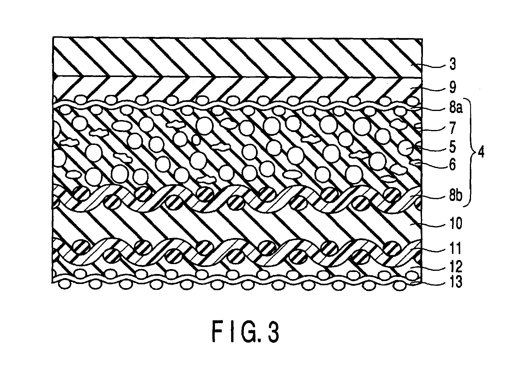
[0102]A cotton fabric sheet 8b included in the compressible printing layer 4 was coated with the rubber paste for adhesive in a thickness of 0.05 mm so as to form an unvulcanizing adhesive layer 10, followed by bonding a cotton fabric sheet 11 used as a first f...


PUM

PropertyMeasurementUnit
melting pointaaaaaaaaaa

Abstract

The present invention provides a manufacturing method of a compressible printing layer, comprising a vulcanizing step comprising a first heating process in which one surface of a compressible printing layer including an unvulcanized compressible layer containing microcapsules is heated by bringing the one surface of the compressible printing layer into contact with the surface of at least one heated metal roll while applying tension to the compressible printing layer, and a second heating process in which the other surface of the compressible printing layer is heated by bringing the other surface of the compressible printing layer into contact with the surface of at least one heated metal roll while applying tension to the compressible printing layer.

Description

CROSS-REFERENCE TO RELATED APPLICATIONS[0001]This is a Continuation Application of PCT Application No. PCT / JP01 / 10616, filed Dec. 5, 2001, which was not published under PCT Article 21(2) in English.BACKGROUND OF THE INVENTION[0002]1. Field of the Invention[0003]The present invention relates to a manufacturing method of a compressible printing layer and a manufacturing method of a blanket for printing.[0004]2. Description of the Related Art[0005]Four manufacturing methods of a compressible layer of a compressible rubber blanket, which is an example of the blanket for printing, are known to the art, including (1) a method using an impregnated paper sheet, (2) a salt leaching method, (3) a foaming agent method, and (4) a microcapsule method. In recent years, a blanket equipped with a compressible layer manufactured by the microcapsule method attracts attentions.[0006]Jpn. Pat. Appln. KOKAI Publication No. 6-1091 discloses a method of manufacturing a compressible rubber blanket includin...

Claims


Application Information

Patent Timeline
Patent Type & Authority Patents(United States)
IPC IPC(8): B29C65/02B41N10/02
CPCB29B13/023B29C35/0266B29C35/0277B29C43/22B32B25/08B32B25/10B41N10/02B41N10/04B29K2021/00B32B2250/04B32B2250/40B32B2307/75B41N2210/02B41N2210/14
Inventor OGAWA, YOSHIHARUINOUE, AKIYOSHISATO, ATSUOUCHIOKE, SHIGERU
Owner KINOYOSHA CO LTD
Why Eureka
Try Eureka