Thermionic electric converter

a technology of electric converter and thermal energy, which is applied in the direction of generator/motor, magnetic discharge control, nuclear engineering, etc., can solve the problems of difficult to maintain the temperature take a significant amount of energy to maintain the high temperature, and difficult to maintain the heat of the cathode and the anode at substantially different temperatures, etc., to achieve the effect of enhancing the output of electrons

Inactive Publication Date: 2006-10-31
THERMOCON
View PDF22 Cites 3 Cited by
  • Summary
  • Abstract
  • Description
  • Claims
  • Application Information

AI Technical Summary

Benefits of technology

[0010]A further principal object of the present invention is provide a thermionic electric converter with improved conversion efficiency.
[0012]Yet another object of the present invention is to provide a thermionic electric converter in which the cathode is bombarded by a laser to increase the emissivity of the cathode.
[0015]The cathode may be either a solid material or formed of a wire grid. When the wire grid construction is used, the wire grid preferably includes at least four layers of wires. Further, each of the wire layers has wires extending in a different direction from each of the other of the wire layers, the wire grid of the cathode thus including wires extending in at least four different directions. This is designed to greatly increase the emissive surface of the cathode.
[0018]The present invention also involves the use of a laser positioned to impinge upon the cathode while being rastered or stepped along the cathode emissive surface, for the purpose of enhancing the output of electrons emitted from the cathode. The laser may be positioned behind the anode or target and aimed at the cathode, and the laser beam may be emitted through an opening in the target to impinge on the cathode. A target or anode specially designed to have an opening therein, preferably through the center thereof, is provided to accommodate the operation of the laser.

Problems solved by technology

With the cathode and anode so close together, it is difficult to maintain the temperatures of the cathode and anode at substantially different temperatures.
Even though the chamber is maintained at a vacuum (other than the cesium source), heat from the cathode goes to the anode and it takes a significant amount of energy to maintain the high temperature differential between the closely spaced cathode and anode.
This in turn lowers the efficiency of the system substantially.

Method used


Image

  • Thermionic electric converter
  • Thermionic electric converter
  • Thermionic electric converter

Examples


Embodiment Construction

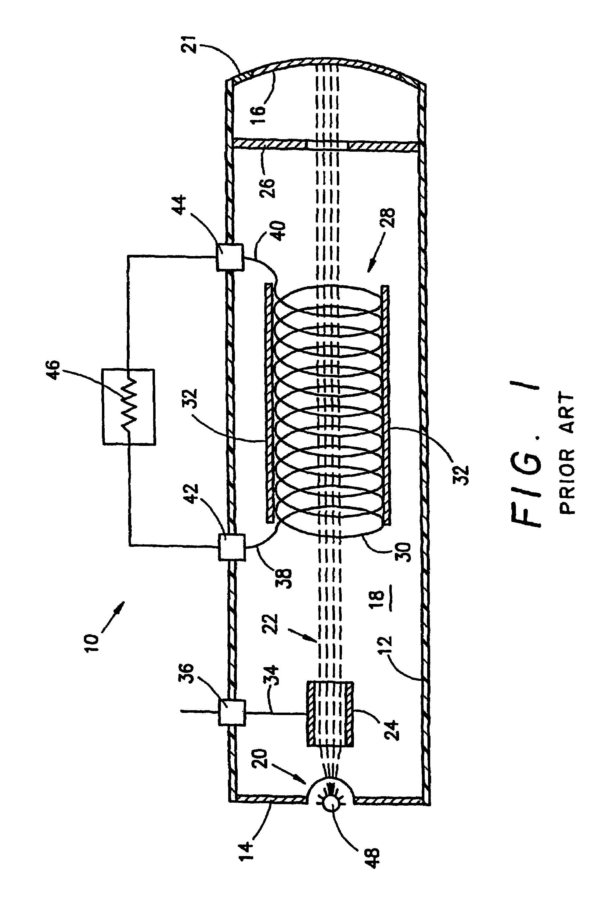
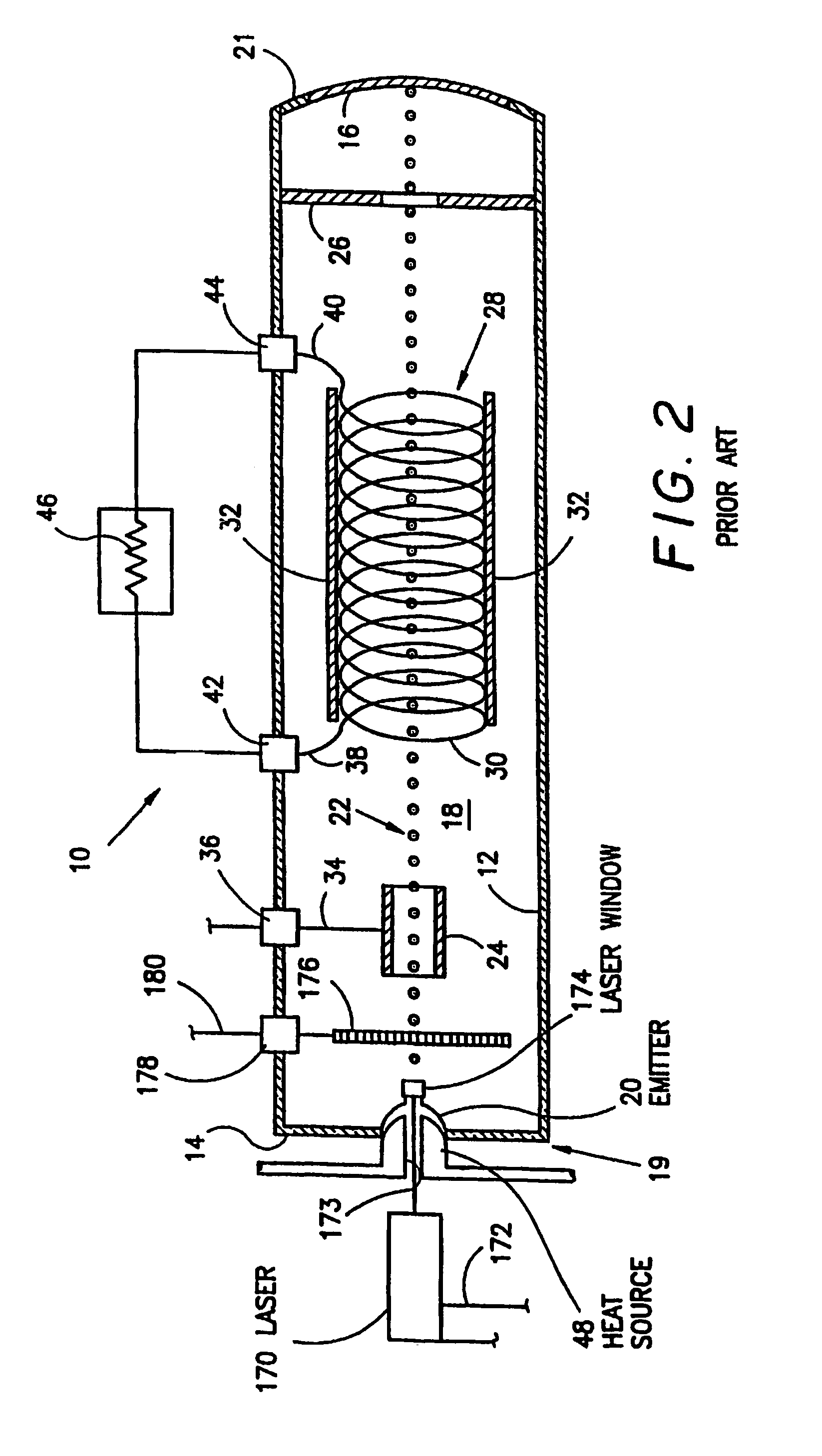
[0031]FIGS. 1 and 2 show prior art thermionic electric converters as shown and described in U.S. Pat. Nos. 4,303,845 and 4,323,808, respectively, both to Edwin D. Davis, the inventor of the present invention, the disclosures of which are incorporated by reference herein in their entirety. While the operation of both thermionic converters is described in detail in the incorporated patents, a general operational overview is presented herein with reference to FIGS. 1 and 2. This may provide background useful in understanding the present invention.

[0032]FIG. 1 shows a basic thermionic electric converter. FIG. 2 shows a laser-excited thermionic converter. The operation of both converters is very similar.

[0033]With reference to the figures, a basic thermionic electric converter 10 is shown. The converter 10 has an elongated, cylindrically shaped outer housing 12 fitted with a pair of end walls 14 and 16, thereby forming a closed chamber 18. The housing 12 is made of any of a number of kno...


PUM


Abstract

A thermionic electric converter includes a cathode output enhancing laser (374) operable to direct a laser beam (376) to strike an emissive surface of a cathode emitter (321), to increase the electron output of the cathode emitter (321). The cathode output enhancing lase (374) is positioned to direct a laser beam (375) through an opening (370) in the anode (306) or target structure, in the direction of the cathode emitter (321). An electron repulsion ring (380) is provided at an edge of the opening (370) in the anode (306), to reduce the number of electrons missing the anode (306) and passing through the opening (370) in the anode (306).

Description

FIELD OF THE INVENTION[0001]The present invention relates generally to the field of converting heat energy directly to electrical energy. More particularly, a thermionic electric converter is provided.BACKGROUND OF THE INVENTION[0002]Heretofore, there have been known thermionic converters such as those shown in U.S. Pat. Nos. 3,519,854, 3,328,611, 4,303,845, 4,323,808, 5,459,367, 5,780,954 and 5,942,834 (all to the inventor of the present invention and all hereby incorporated by reference), which disclose various apparatus and methods for the direct conversion of thermal energy to electrical energy. In U.S. Pat. No. 3,519,854, there is described a converter using Hall effect techniques as the output current collection means. The '854 patent teaches use of a stream of electrons boiled off of an emissive cathode surface as the source of electrons. The electrons are accelerated toward an anode positioned beyond the Hall effect transducer. The anode of the '854 patent is a simple metall...

Claims


Application Information

Patent Timeline
Patent Type & Authority Patents(United States)
IPC IPC(8): H02N10/00H01J45/00
CPCH01J45/00
Inventor DAVIS, EDWIN D.
Owner THERMOCON
Why Eureka
Try Eureka