Uninterrupted power supply and the method for driving its converters

a technology of uninterrupted power supply and converter, which is applied in emergency power supply arrangements, process and machine control, instruments, etc., can solve the problems of low system reliability, inability to exceed 20 khz switching frequency, and restricted input voltage, so as to improve system reliability, improve system bandwidth, and improve the effect of transient response to output voltag

Inactive Publication Date: 2006-10-31
EMERSON NETWORK POWER CO LTD
View PDF5 Cites 8 Cited by
  • Summary
  • Abstract
  • Description
  • Claims
  • Application Information

AI Technical Summary

Benefits of technology

[0005]An object of the present invention is to solve the aforesaid problems by providing an uninterrupted power supply having symmetrical converters connected in parallel, and a method for driving the converters, thereby improving the uniform current in the system.
[0006]Another object of the present invention is to increase the capability of dynamic response of the system.
[0007]The other object of the present invention is to increase the input voltage range.
[0013]With the aforesaid solution that introduces a pulse-width maintaining circuit, the present invention can keep the currents of the switch transistors of the two parallel boost converters substantially the same, thereby improving the reliability of the system.
[0014]Further, the sampling signals of the induced currents of the positive and negative boost converters in the power factor correction branch come from one of the inductors in the parallel positive boost converters and one of the inductors in the parallel negative boost converters respectively, rather than sampling the overall current of the two parallel inductors, thereby allowing the electric current loop to work in a single boost converter situation. As a result, the bandwidth of the system can be increased, and the transient response to output voltage can be significantly improved as well. In case the DC power supply and the change-over switches are further provided, the input voltage range can be increased.

Problems solved by technology

Although these controlling strategies may effectively improve the input power factor, they have their respective drawbacks.
However, a drawback of this strategy is that the input voltage is restricted and the switching frequency cannot exceed 20 KHz in high power applications.
However, there is only replacement without holding the width of the Pulse it may result in uneven current of those two voltage increase converters, and thus the system reliability is low.

Method used


Image

  • Uninterrupted power supply and the method for driving its converters
  • Uninterrupted power supply and the method for driving its converters
  • Uninterrupted power supply and the method for driving its converters

Examples


Embodiment Construction

[0019]The present invention is described below in detail in conjunction with the embodiment and the accompanying drawings.

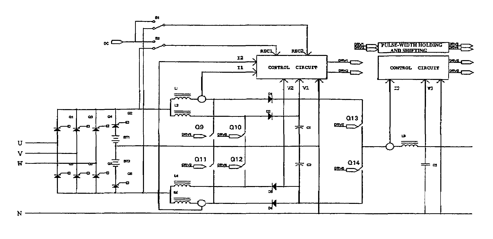
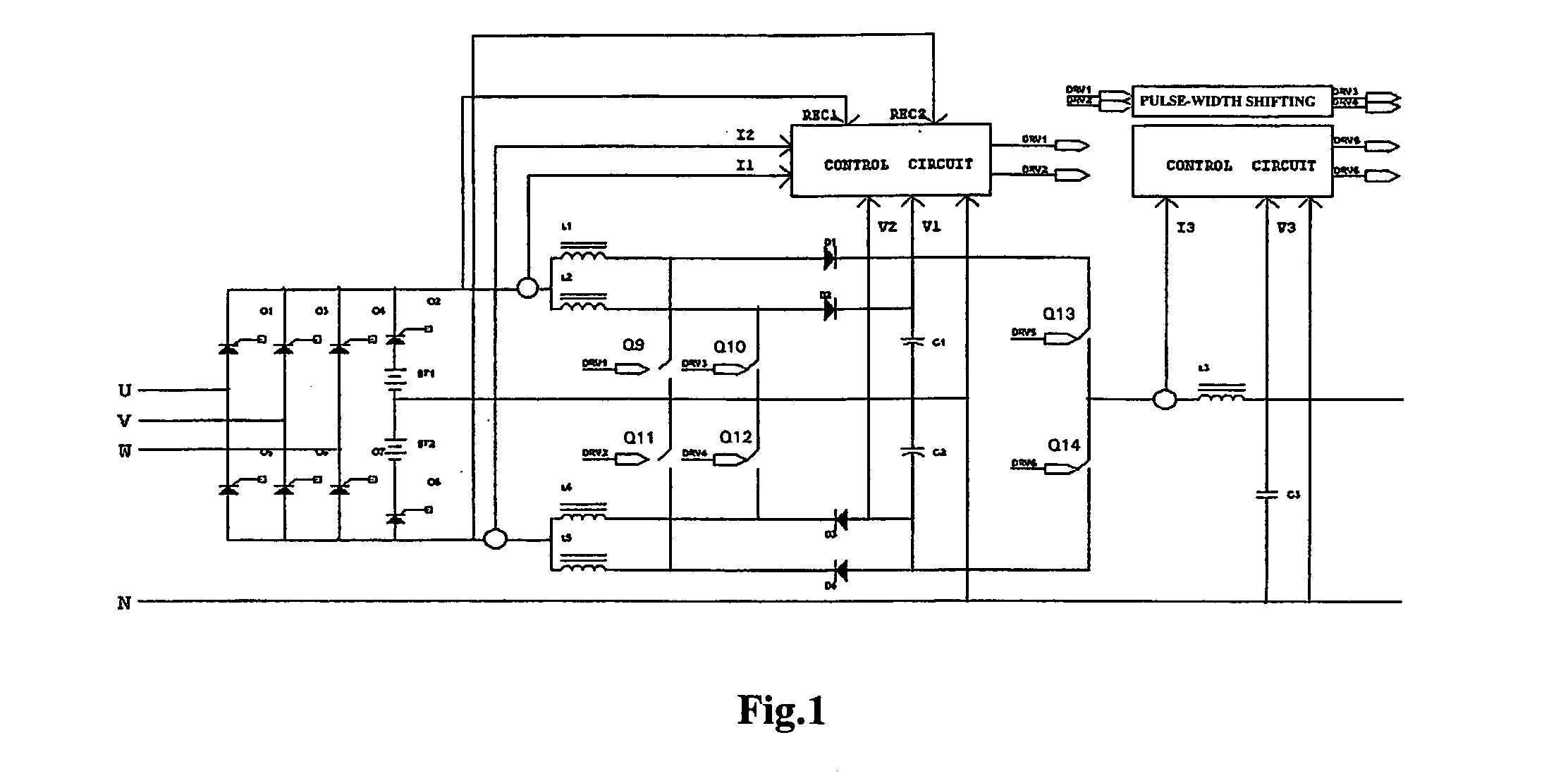
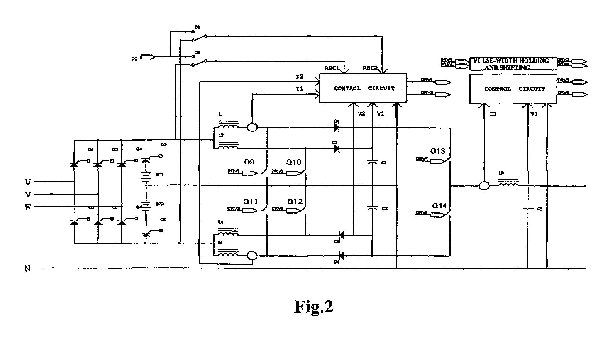
[0020]FIG. 2 shows an embodiment of the present invention, and the basic principle thereof is similar with that illustrated in FIG. 1. It achieves the high quality input current waveform and reduces the input harmonic current by detecting the induced current signals, and forward-feeding the voltage waveform after the rectification bridge, that is, the positive and negative voltage output sampling signals (REC1, REC2) after the voltage is rectified. The circuit construction is similar to that of the conventional mean value controlling technology, which can be referred to as mean value current injection control method. This method can be a single-phase mean value current injection control or a three-phase mean value current injection control where the rectifying circuit and AC input end are three-phase four-wire systems. The present invention takes the three-phase ...


PUM


Abstract

This invention relates to a method for driving converts of an uninterrupted power supply (UPS), characterized in that the generating circuit of driving signal for power factor correction generates two driving signals (DRV1, DRV2) to drive the switch transistors (Q9, Q11) of the positive and negative power factor correction branch respectively, the holding and shifting circuit of driving pulse-width after the generating circuit of driving signal for power factor correction holds and shifts the pulse-width of the two driving signals, and drives the switch transistors (Q10, Q12) parallel to the aforesaid switch transistors in the positive and negative power factor correction branch respectively. Since a circuit for holding the pulse-width is introduced, the currents of the switch transistors of the two parallel boost converters are maintained substantially the same, thereby improving the reliability of the uninterrupted power supply system. As a result, this invention can be widely used in any application where a UPS is desired.

Description

TECHNICAL FIELD[0001]The present invention relates to an uninterrupted power supply (UPS) and a method for driving its converters. More particularly, it relates to an uninterrupted power supply having a power factor correction (PFC) circuit and symmetrical converts connected in parallel and a method for driving such converters.BACKGROUND OF THE INVENTION[0002]Recently, an UPS of three-phase four-wire high-frequency link has been proposed in some controlling strategies, which include peak value current control and mean value current control, etc. With such improved controlling strategies, the content of the quintic or septic harmonic waves and the like can be significantly reduced. Although these controlling strategies may effectively improve the input power factor, they have their respective drawbacks. In case of the peak value current controlling strategy, the wave shapes of the three-phase input currents are different from each other, and the overall current of the harmonic waves ...

Claims


Application Information

Patent Timeline
Patent Type & Authority Patents(United States)
IPC IPC(8): H02M1/12H02J9/06H02M1/00H02M1/42
CPCH02M1/4208H02M1/4216H02J9/06Y02B70/126Y02B70/10Y02P80/10
Inventor YANG, GEGE
Owner EMERSON NETWORK POWER CO LTD
Why Eureka
Try Eureka