
Fluoroscopic image guided orthopaedic surgery system with intraoperative registration

a fluoroscopic image and orthopaedic surgery technology, applied in the field of orthopaedic surgery, can solve the problems of inaccurate actual aiming of the fixation device, difficult to determine the angular approach, time-consuming method, etc., and achieve the effect of simplifying the operation, reducing operative time and radiation, and superior results

Inactive Publication Date: 2006-10-31
SOFAMOR DANEK PROPERTIES
View PDF433 Cites 283 Cited by
  • Summary
  • Abstract
  • Description
  • Claims
  • Application Information

AI Technical Summary

Benefits of technology

[0011]The present invention allows an orthopaedic surgeon to safely determine the precise trajectory of insertion of a fixation device into an object bone and to check the accuracy of the procedure using real time feedback.
[0015]The difference from prior art is that, in this invention, distinctly shaped radiographic markers are not required to match the position of the object bone with the image thereof. Matching, or registration, is performed by a single registration pin or other object that is seen on both x-ray views. The spherical shape of the femoral head may be used to increase the accuracy of the registration if the invention is used for hip surgery. When used for inserting distal locking screws for intramedullary nails, the presence of the nail alone with the holes for the interlocking screws can be used as fiducial reference marker. This method of image registration is clearly superior to the use of three special registration pins with specialized markers.
[0017]Accurate localization of a hip screw in the femoral head has been shown in an important clinical study to result in much superior results than if the screw is placed eccentrically. Accurate aiming of an interlocking screw in an intramedullary nail is difficult to obtain using all current techniques. It is improved by this invention such that operative time and radiation are markedly reduced.
[0018]This invention has the advantage of simplifying the operation and making it more acceptable to use computer assisted surgery to improve accuracy.

Problems solved by technology

However, in practice the actual aiming of a fixation device is an inaccurate art, as the object bone is often seen only at one surface or is not seen at all and, therefore, positioning is dependent on fluoroscopic visualization.
This method is also time consuming as the C-arm images must be taken separately and the drapes must be rearranged each time an image is taken.
This angular approach is difficult to determine under normal circumstances and often multiple attempts are needed, as feedback is obtained from repeated fluoroscopic images.
Radiation exposure is considered to be a hazard.
Such imaging studies are routinely performed for most intracranial procedures but are impractical for most orthopaedic procedures, especially those involving long bones.
A disadvantage of this system is that the images are normally obtained hours before use; thus, the images used are not up to date (real time) and are often not reflective of the current condition of the object bone.
Registration markers cannot be used on the outside of the body in most orthopaedic cases as the skin does not adhere to the underlying bone.
Such a separate procedure is highly impractical for routine orthopaedic procedures.

Method used


Image

  • Fluoroscopic image guided orthopaedic surgery system with intraoperative registration
  • Fluoroscopic image guided orthopaedic surgery system with intraoperative registration
  • Fluoroscopic image guided orthopaedic surgery system with intraoperative registration

Examples


Embodiment Construction

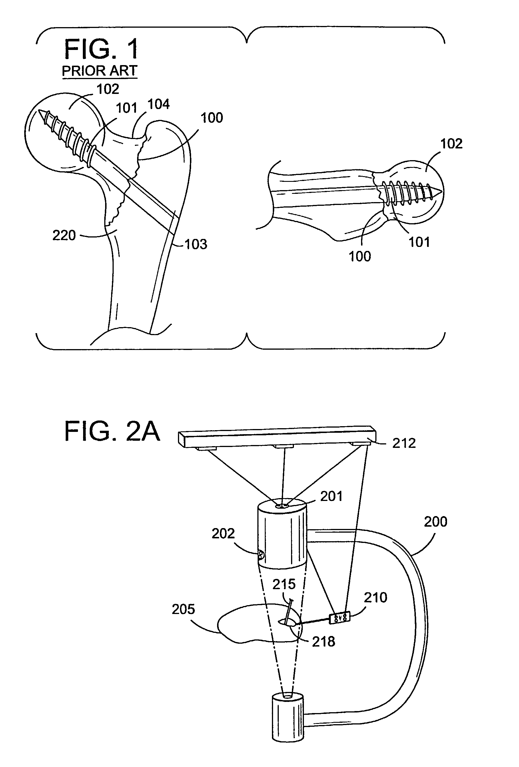
[0023]The operation for the internal fixation of intertrochanteric hip fracture 100 requires a guide pin for a cannulated hip screw, and subsequently cannulated screw 101, to be placed into femoral head 102 from lateral cortex 103 of proximal femur 220 via femoral neck 104, as illustrated in FIG. 1. Guide pin 302 for cannulated hip screw 101 determines the position of cannulated screw 101. The ideal position of the guide pin for a cannulated hip screw, and thus screw 101, is entirely within bone. The end of the pin, and screw 101, is best positioned very near the subcortical bone but should not penetrate the cortex and thus enter the hip joint. The best results of an intertrochanteric fracture 100 must have been shown to occur when large screw 101 used is in the center of the femoral head at the subcortical bone. This position is normally obtained by placing the guide pin for a cannulated hip screw by estimation and by following its course on entry with repeated x-rays views in two ...


PUM


Abstract

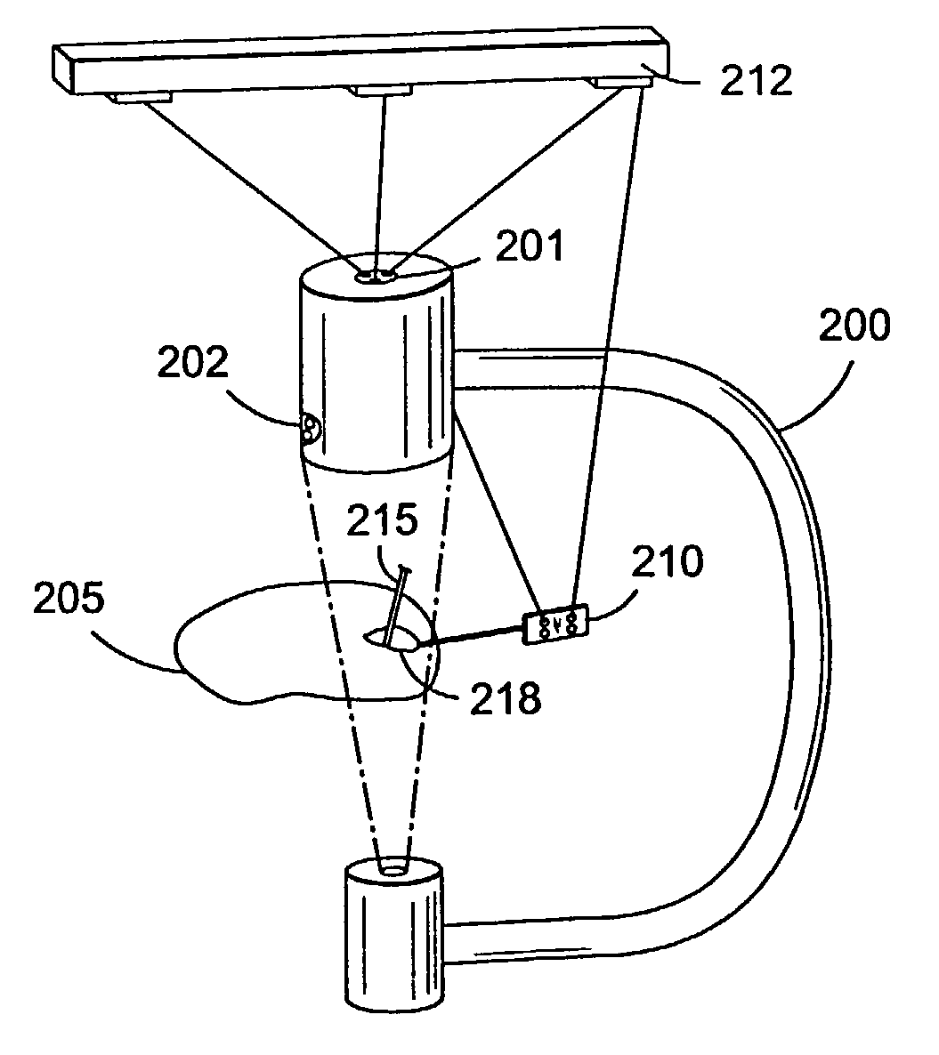
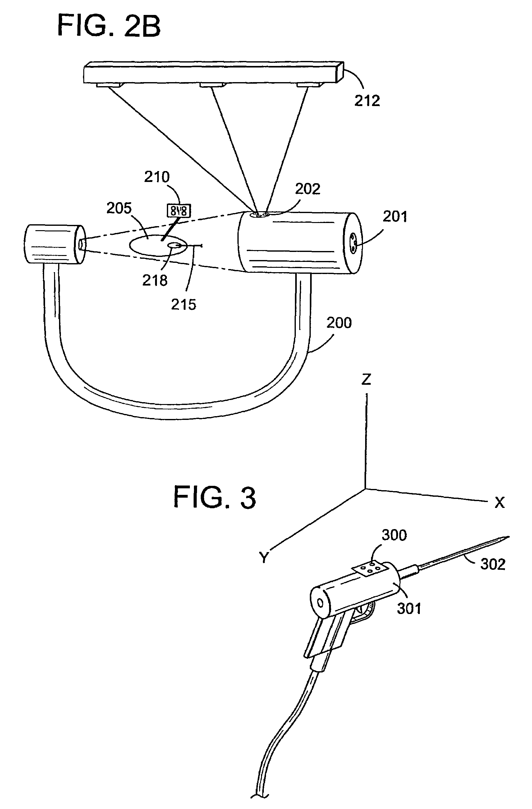
A fluoroscopic image guided surgery system, comprising a C-arm fluoroscope for obtaining fluoroscopic images of an object bone, the C-arm fluoroscope including at least one set of emitters; a reference bar capable of attaching to an object bone, the reference bar including emitters; a surgical instrument for performing an operation, the instrument including emitters; a digitizer system in communication with the at least one set of emitters of the C-arm fluoroscope, the emitters of the reference bar, and the emitters of the surgical instrument so that the digitizer system can determine a position of each of the C-arm fluoroscope, the reference bar, and the surgical instrument; and a single fiducial marker for attachment to an object bone, the single fiducial marker being visible in the fluoroscopic images for determining a position of an object bone relative to the digitizer system.

Description

CROSS-REFERENCE TO RELATED APPLICATIONS[0001]This application is a continuation of U.S. patent application Ser. No. 09 / 376,712, filed on Aug. 16, 1999, now U.S. Pat. No. 6,477,400, issued on Nov. 5, 2002, which claims the benefit of both U.S. Provisional Application Ser. No. 60 / 097,742, filed on Aug. 24, 1998 and U.S. Provisional Application Ser. No. 60 / 097,183, filed on Aug. 20, 1998.BACKGROUND OF THE INVENTION[0002]In orthopaedic surgery it is often necessary to insert a guide pin for a cannulated screw, drill bit, or other screw (hereafter referred to as a fixation device) into a bone at a predetermined trajectory. Pre-operative planning depends on two-dimensional radiographic images which typically consist of two views taken at approximately right angles to one another. From these two views it is possible to determine the shape and structure of a long bone. Using that method, the path of insertion for a guide pin for a cannulated screw, drill bit, or screw is accurately determin...

Claims


Application Information

Patent Timeline
Patent Type & Authority Patents(United States)
IPC IPC(8): A61B5/00A61B6/00A61B6/12A61B17/17A61B19/00
CPCA61B5/064A61B6/12A61B6/4441A61B6/547A61B17/1703A61B17/1721A61B19/52A61B19/5244A61B5/4528A61B17/1742A61B17/1757A61B2019/507A61B2019/5238A61B2019/5255A61B2019/5272A61B2019/5287A61B90/36A61B2034/2055A61B2034/2072A61B2090/363A61B34/20A61B2090/376A61B2034/107
Inventor BARRICK, EARL F
Owner SOFAMOR DANEK PROPERTIES
Learn More