
Method and apparatus for controlling an internal combustion engine using accelerometers

a technology of accelerometer and internal combustion engine, which is applied in the direction of machines/engines, vehicle components, process and machine control, etc., can solve the problems of insufficient accuracy of pressure signal reconstruction method, lack of reliability and robustness, and high cost of optical sensors or other direct pressure measurement instruments

Active Publication Date: 2006-11-07
WESTPORT FUEL SYST CANADA INC
View PDF8 Cites 29 Cited by
  • Summary
  • Abstract
  • Description
  • Claims
  • Application Information

AI Technical Summary

Benefits of technology

[0008]Once estimated, this SOC information can be used to vary one of a number of levers ava...

Problems solved by technology

Optical sensors, or other direct pressure measurement instruments, can be expensive and may lack the reliability and robustness (due to the harsh environment within a combustion chamber) required for the application.
However, the drawback with U.S. Pat. No. 6,408,819 is that this technique relies on a method of reconstructing a pressure signal that is unlikely to be sufficiently accurate.
The non-linearity introduced by cepstral filtering creates complexities when correlating parameters to SOC.
The result can be higher errors in the estimated SOC for a given cycle of the engine.
Relying on a standard pressure reconstruction technique would result in a relatively inaccurate picture of the in-cylinder pressure prior to combustion.
That is, the use of an accelerometer may not give an accurate measure of the in-cylinder pressure prior to combustion, and hence can lead to problems in applying the technique proposed in U.S. Pat. No. 6,598,468.

Method used


Image

  • Method and apparatus for controlling an internal combustion engine using accelerometers
  • Method and apparatus for controlling an internal combustion engine using accelerometers
  • Method and apparatus for controlling an internal combustion engine using accelerometers

Examples


Embodiment Construction

[0032]A method is provided for controlling the start of combustion (SOC) of a fuel within a combustion chamber of an internal combustion engine.

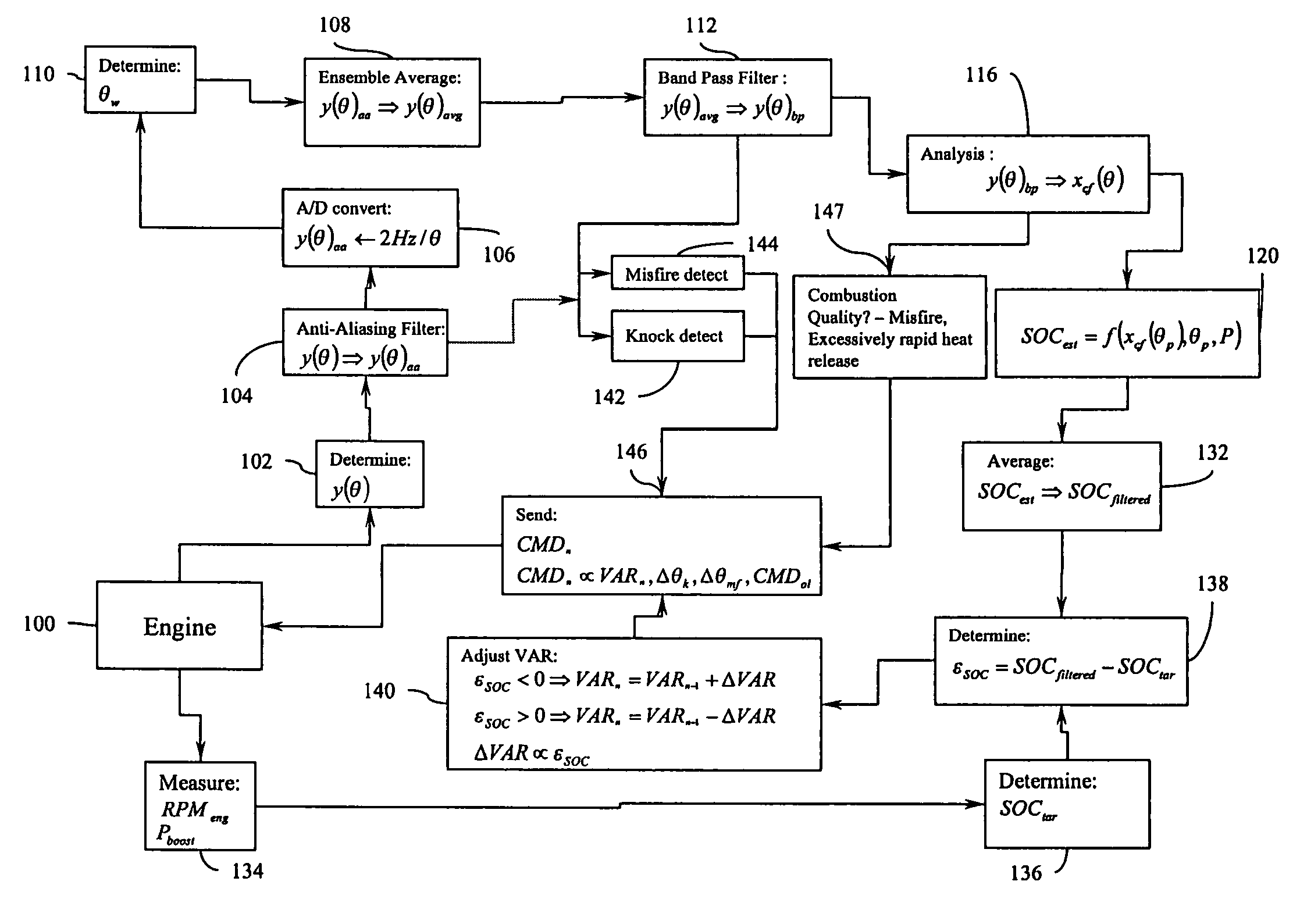
[0033]Referring to FIG. 1, a flow diagram is provided setting out the subject method used to control the start of combustion in an internal combustion engine. Reference is made to engine 100 where accelerometer signals 102 (y(θ)) are first determined by an accelerometer across a window of selected crank angle degrees (θ) for a cycle of an engine. These values can be filtered with an anti-aliasing filter 104, converted to a digital data set 106, and windowed. The crank angle window (θw) can be predetermined and in light of the engine properties and operating conditions, step 110. The windowed data can be averaged across the same selected window of crank angle degrees for several engine cycles with an ensemble-averaging filter 108. A band pass filter 112 can be applied to the averaged and windowed digital knock signal (y(θ)avg) resulting in ba...


PUM


Abstract

A method for processing an accelerometer data set generated from an operating internal combustion engine is disclosed. The processed accelerometer data is cepstrally filtered and a heat release trace is pulled from the accelerometer data set. That heat release trace is then used to estimate combustion quality and combustion phasing within the engine and control future combustion events using this information. Misfire and knock sensing is also incorporated into the engine controls. The method provides controls for an engine to allow it to adjust combustion from cycle window to cycle window generally without the need for expensive and less durable direct pressure measurement devices as compared to accelerometers. The resulting fuel injection speed results in the fuel passing through shock waves within the combustion chamber, which, in turn, promotes combustion of the fuel by promoting mixing of the fuel and intake charge within the combustion chamber.

Description

RELATED APPLICATIONS[0001]This application claims priority of Provisional Application Ser. No. 60 / 483,855, entitled “Method and Apparatus for Controlling an Internal Combustion Engine Using Accelerometer,” filed Jun. 30, 2003, which is hereby incorporated by reference in its entirety.BACKGROUND OF THE INVENTION[0002]Internal combustion engines benefit from real time estimation of combustion quality and start of combustion (SOC). Knowing when combustion commences can help provide a control strategy that adjusts the SOC in future engine cycles to allow for improved performance of the engine. One engine that benefits substantially from SOC monitoring or estimation, is an engine that relies on the auto-ignition of a pre-mixed fuel and air charge. The auto-ignition of a pre-mixed fuel and air charge is referred to here as pre-mixed charge compression ignition, or PCCI. There tends to be emissions and efficiency benefits with PCCI combustion modes over typical diffusion or flame propagati...

Claims


Application Information

Patent Timeline
IPC IPC(8): B60T7/12F02B1/12F02D35/02F02D41/00F02D41/14F02D41/30F02P5/15
CPCF02D35/028F02D41/1497F02P5/15F02P5/1512F02D35/027F02B1/12Y02T10/36F02D41/0027F02D41/3035F02D41/3041F02D2041/288F02D2041/389F02D2200/025Y02T10/46F02D19/10Y02T10/30Y02T10/40F02D35/02
Inventor ANCIMER, RICHARD
Owner WESTPORT FUEL SYST CANADA INC
Learn More