Exhaust emission control and diagnostics

a technology of exhaust emission control and diagnostics, applied in electrical control, separation processes, machines/engines, etc., can solve problems such as the detection of degradation by sensors, and achieve the effect of reducing nox conversion

Inactive Publication Date: 2006-11-14
FORD GLOBAL TECH LLC
View PDF9 Cites 66 Cited by
  • Summary
  • Abstract
  • Description
  • Claims
  • Application Information

AI Technical Summary

Benefits of technology

[0013]By monitoring whether the preselected ratio is within acceptable limits, it is possible to determine when sulfur degradation can result in the downstream catalyst due to degradation of maintaining the preselected N

Problems solved by technology

Further, if the ratio is not maintained,

Method used


Image

  • Exhaust emission control and diagnostics
  • Exhaust emission control and diagnostics
  • Exhaust emission control and diagnostics

Examples


Embodiment Construction

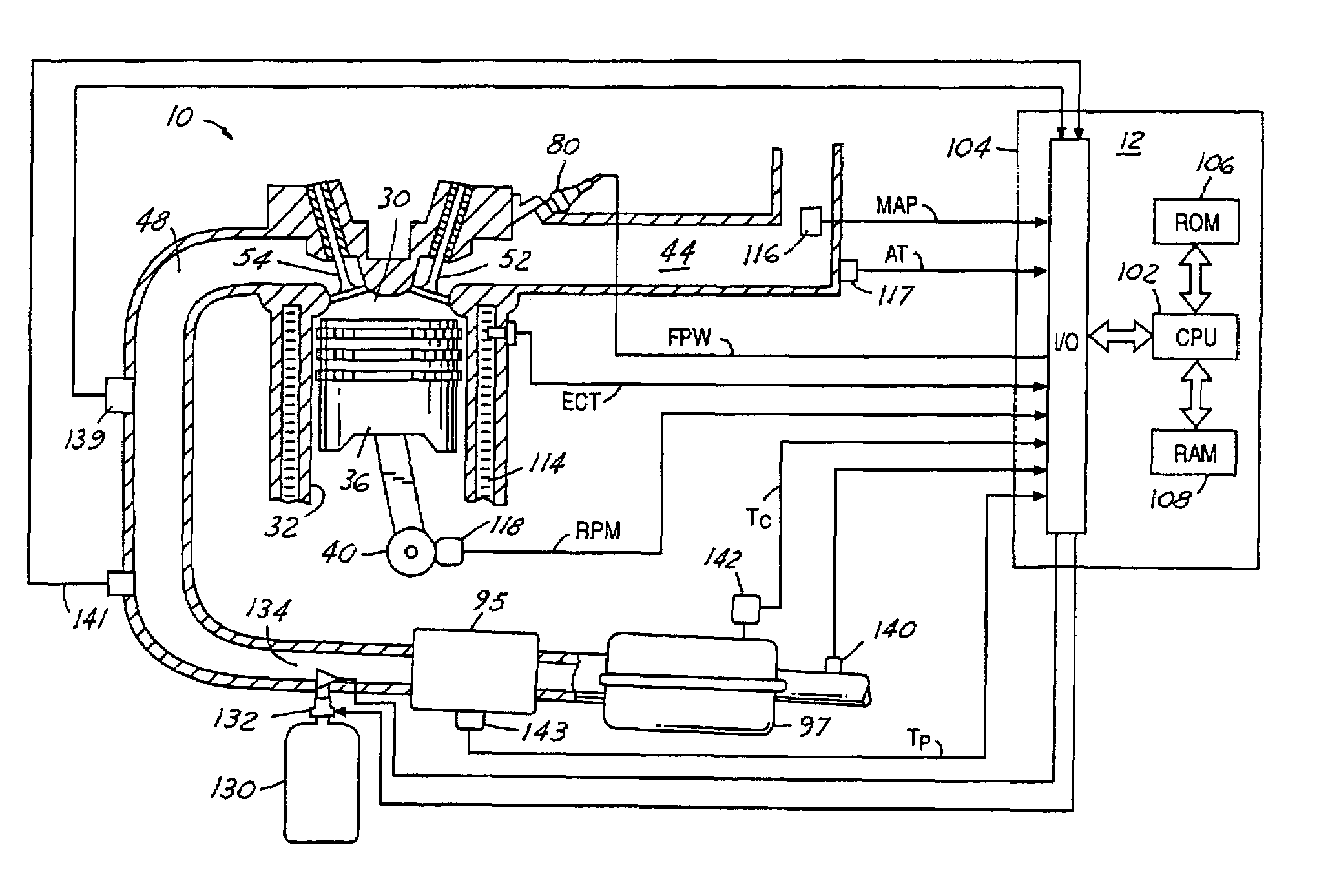
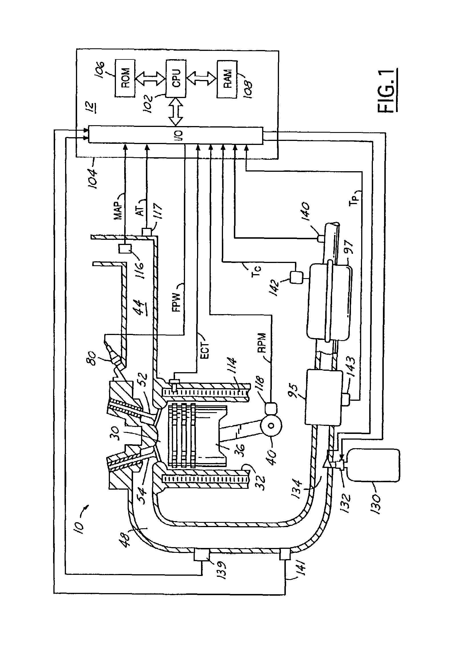
[0019]Internal combustion engine 10, comprising a plurality of cylinders, one cylinder of which is shown in FIG. 1, is controlled by electronic engine controller 12. Engine 10 includes combustion chamber 30 and cylinder walls 32 with piston 36 positioned therein and connected to crankshaft 40. Combustion chamber 30 is shown communicating with intake manifold 44 and exhaust manifold 48 via respective intake valve 52 and exhaust valve 54. Intake manifold 44 is also shown having fuel injector 80 coupled thereto for delivering liquid fuel in proportion to the pulse width of signal FPW from controller 12. Fuel quantity, controlled by signal FPW, and injection timing are both adjustable. Fuel is delivered to fuel injector 80 by a diesel fuel system (not shown), including a fuel tank, fuel pump, and fuel rail (not shown). The fuel contained in the fuel system includes various impurities and, in particular, varying amounts of sulfur. As described herein, sulfur has consistently cause disadv...


PUM

PropertyMeasurementUnit
Temperatureaaaaaaaaaa
Ratioaaaaaaaaaa
Speedaaaaaaaaaa

Abstract

A diesel engine emission control system uses an upstream oxidation catalyst and a downstream SCR catalyst to reduce NOx in a lean exhaust gas environment. The engine and upstream oxidation catalyst are configured to provide approximately a 1:1 ratio of NO to NO2 entering the downstream catalyst. In this way, the downstream catalyst is insensitive to sulfur contamination, and also has improved overall catalyst NOx conversion efficiency. Degradation of the system is determined when the ratio provided is no longer near the desired 1:1 ratio. This condition is detected using measurements of engine operating conditions such as from a NOx sensor located downstream of the catalysts. Finally, control action to adjust an injected amount of reductant in the exhaust gas based on the actual NO to NO2 ratio upstream of the SCR catalyst and downstream of the oxidation catalyst.

Description

CROSS REFERENCE TO RELATED APPLICATIONS[0001]This invention was made with Government support under Prime Contract No. DE-FC26-01NT41103 awarded by the Department of Energy. The Government has certain rights in the invention. This application is cross-referenced to a related application (202-0638) being filed concurrently herewith and having Ser. No. 10 / 064,956.BACKGROUND OF INVENTION[0002]1. Field of the Invention[0003]The present invention relates to selective catalytic reduction, and more particularly to methods for controlling and diagnosing such catalytic reduction as well as for controlling internal combustion diesel engines attached to such catalyst systems.[0004]2. Background of the Invention[0005]Diesel internal combustion engines typically operate predominantly lean of stoichiometry. As such, various emission control devices have been used to reduce NOx emissions generated by the engine operation. One such device is a lean NOx catalyst. One example of such a catalyst is a s...

Claims


Application Information

Patent Timeline
IPC IPC(8): F01N3/00B01D53/94F02M25/07F01N3/08F01N3/20F01N3/28F01N13/02F02D21/08F02D45/00
CPCB01D53/9454B01D53/9495F01N3/208F01N13/009F01N2610/02F01N2610/03F01N2900/0411F01N2900/14Y02T10/22Y02T10/24Y02T10/12
Inventor MAZUR, CHRISTOPHER JOHNUPADHYAY, DEVESH
Owner FORD GLOBAL TECH LLC
Why Eureka
Try Eureka