

Differential pressure transducer with Fabry-Perot fiber optic displacement sensor
a technology of fiber optic displacement sensor and differential pressure transducer, which is applied in the direction of fluid pressure measurement, pressure difference measurement between multiple valves, instruments, etc., can solve the problems of sensor output drift and transducer non-linearity with pressure, inability to detect changes, and inability to accept increased response time. to prevent unwanted damage to the transducer
- Summary
- Abstract
- Description
- Claims
- Application Information
AI Technical Summary
Benefits of technology
Problems solved by technology
Method used
Image

Examples
Embodiment Construction
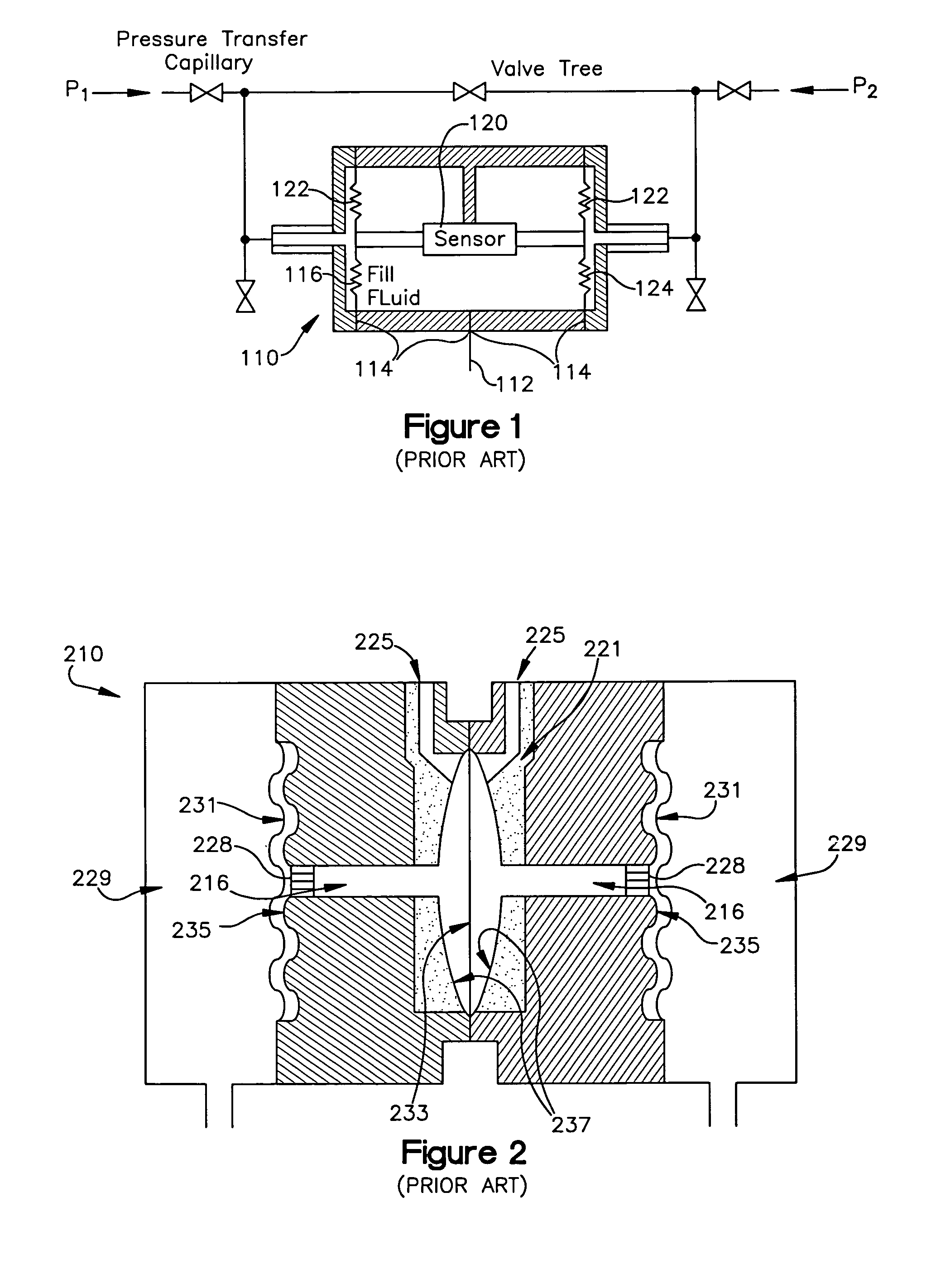
[0030]The present invention provides an alternative to the differential pressure transducers known in the art, and is particularly well-suited replacement for those presented in FIGS. 1 and 2. Additionally, it improves upon previous transducers by providing a Fabry-Perot sensor which quantitatively and directly measures directly measures absolute displacements within the transducer in a non-contact manner and without the use of light intensity calibration curves, which themselves may be negatively influenced by unknown but unwanted problems with the transmission fiber and / or light source. Additionally, the invention represents a significant simplification of design in comparison to previously known transducers that require the positioning of fibers between corrugations or the use of specially designed gratings.
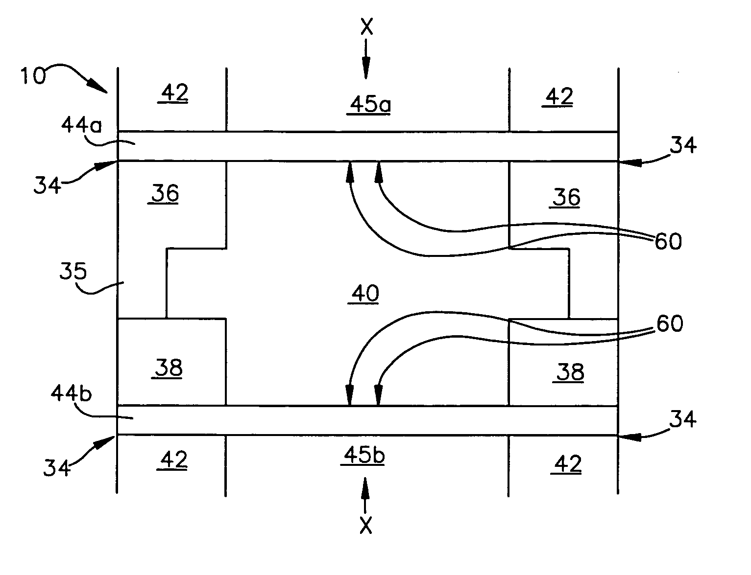
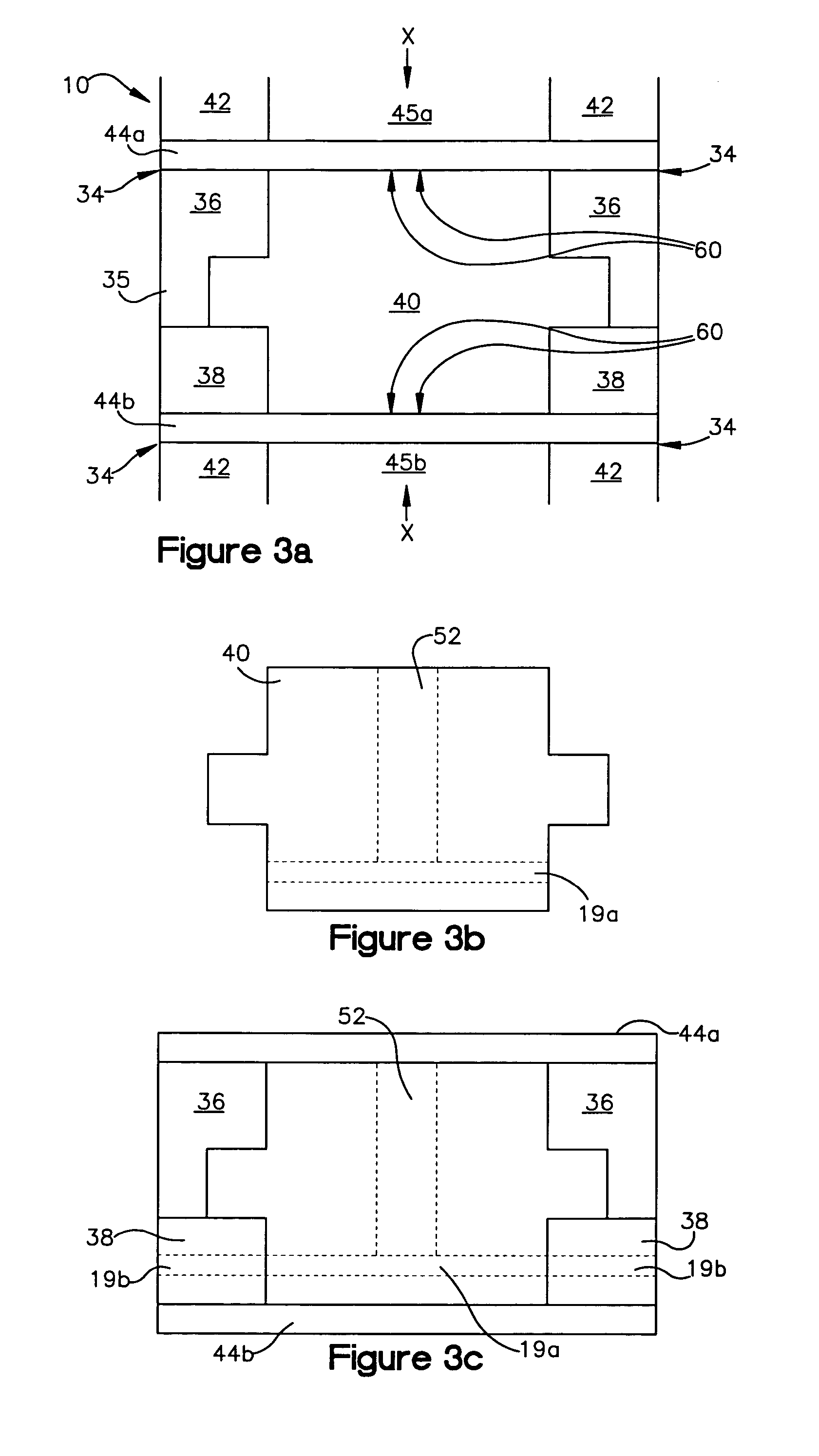
[0031]In the present invention presented in FIG. 3a, fill fluid is not used in the volume between the diaphragms. The internal pressure between the diaphragms is at atmospheri...
PUM
| Property | Measurement | Unit |
|---|---|---|
| operating pressure | aaaaa | aaaaa |
| static pressure | aaaaa | aaaaa |
| pressure | aaaaa | aaaaa |
Abstract
Description
Claims
Application Information