Rotor system for a remotely controlled aircraft

a remote control and rotor technology, applied in the direction of propellers, automatic actuation, water-acting propulsive elements, etc., can solve the problems of heavy motors, heavy weight of the second internal combustion engine, and no model helicopters with a weight of 200 grams have been commercially available, so as to increase bearing friction, increase bearing friction, and strengthen the effect of damping elemen

Inactive Publication Date: 2006-11-14
VOGEL HERIBERT
View PDF6 Cites 9 Cited by
  • Summary
  • Abstract
  • Description
  • Claims
  • Application Information

AI Technical Summary

Benefits of technology

[0007]The at least one coil is preferably driven in a pulsed manner. This allows the angle of incidence to be controlled or regulated, for example, completely digitally.
[0008]Provision is preferably made for the force which causes the adjustment of the angle of incidence of the at least one rotor blade to be transmitted as a torsion force to the rotor blade via a connecting bracket which is hinged on the at least one rotor blade such that the position of the connecting bracket defines the angle of incidence of the at least one rotor blade. In this context, it is, for example, feasible for one connecting bracket to be associated with one rotor blade or for each rotor blade to be associated with one connecting bracket. The last-mentioned solution is used in particular when two or more rotor blades are provided, whose angles of incidence can be varied independently of one another.

Problems solved by technology

A second internal combustion engine, provided only for driving the tail rotor, would be too heavy, in particular in the region of the tail rotor.
Any additional weight in turn requires more powerful and hence necessarily heavier motors and an energy supply for them, for example rechargeable batteries.
This has led to a situation in which, until now, no model helicopters with a weight of <200 grams have been commercially available, for example.
However, experience has shown that those learning to fly them, in particular, have problems in successfully controlling the model inside rooms, so that the expression indoor in fact means hall-type rooms.
When crashes occur, the model is often damaged despite having a robust construction.
Although a number of prototypes of model helicopters are known whose weight is down to 40–50 grams, these prototypes are, however, also based on the conventional technology, are correspondingly complex to manufacture, and are thus not suitable for large-scale production.

Method used


Image

  • Rotor system for a remotely controlled aircraft
  • Rotor system for a remotely controlled aircraft
  • Rotor system for a remotely controlled aircraft

Examples


first embodiment

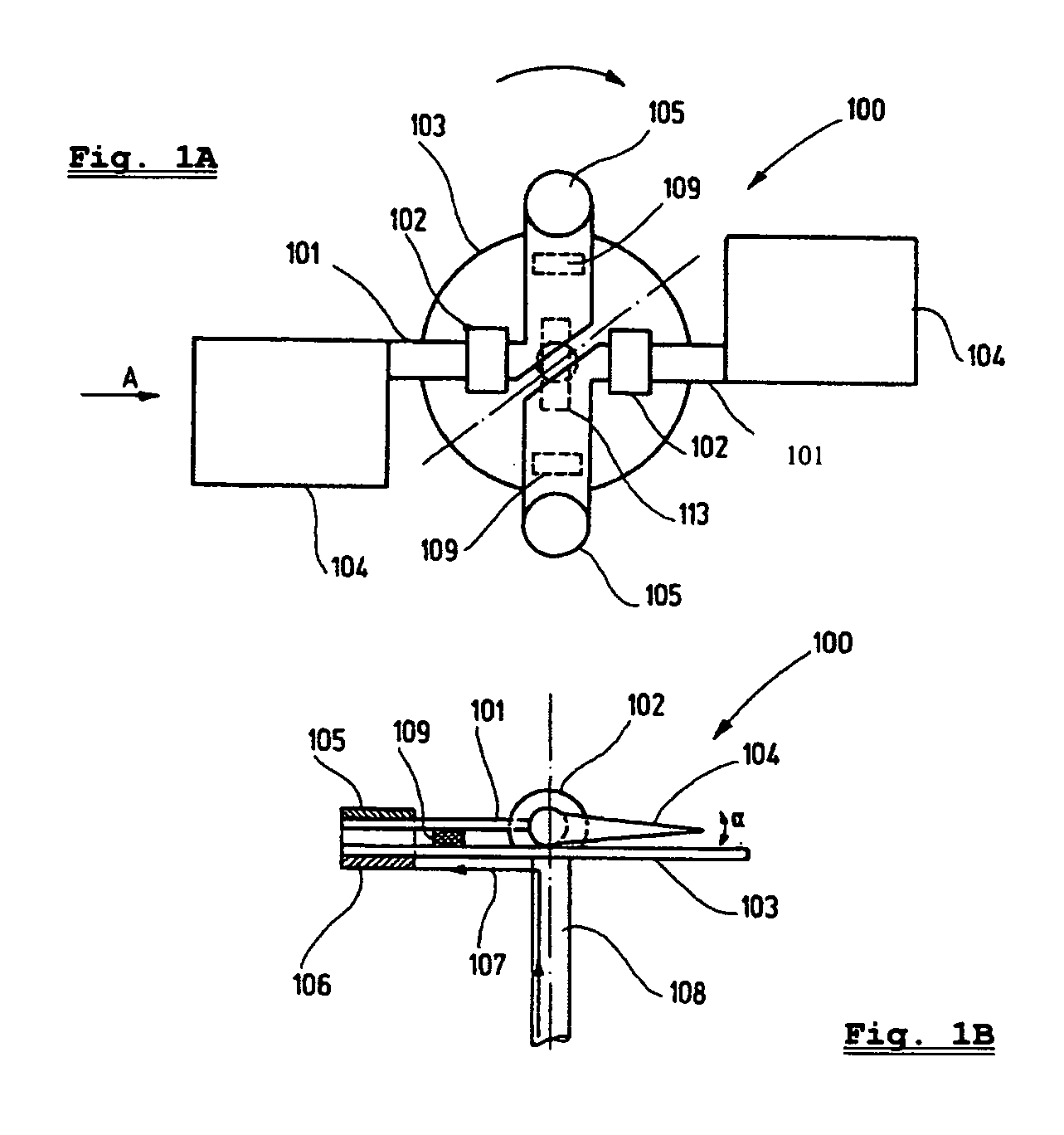
[0042]FIGS. 1A and 1B shows a plan view and side view of a main rotor of the aircraft according to the invention, Two coils 106, which are electrically connected via tap contacts (which are not illustrated), are mounted symmetrically with respect to the main rotor shaft 102 on a main rotor plate 103, which is connected to a main rotor shaft 108 which runs in bearings. Two rotary bearings 102 are likewise mounted on the main rotor plate 103 and each have a connecting bracket 101 mounted in them, to whose opposite ends a permanent magnet 105 and a rotor blade 104 are attached. The permanent magnet 105 is arranged such that a direct current 107 through the coils 106 leads to deflection of the connecting bracket 101 and hence to a change in the angle of incidence α of the rotor blades. The change in the angle of incidence α also results in a change in the speed of the air which is accelerated downward or upward by the rotor blades 104 as the rotor head rotates, and hence also results in...

second embodiment

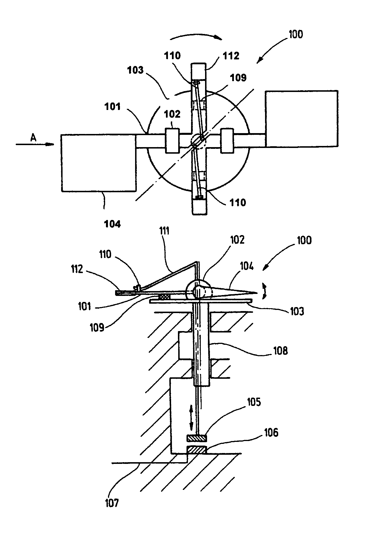
[0045]FIGS. 3A and 3B shows a plan view and a side view of a main rotor of the aircraft according to the invention. In order to avoid sliding contacts, which in some circumstances are susceptible to defects, for producing an electrical connection to the coils 106, the coils 106 are mounted in the non-rotating part of the helicopter in the embodiment illustrated in FIGS. 3A and 3B. The connection between the rotor blades 104 and the permanent magnets 105 is in this case provided via connecting brackets 101, eyes 110 and push rods 111, on which the permanent magnets 105 are mounted. The vertical force which is introduced into the connecting bracket 101 through the push rod 105 via the eye 110 leads to the already described deflection of the connecting bracket 101 and to the described control response, that is to say to the adjustment of the angle of incidence α. In the embodiment illustrated in FIGS. 3A and 3B, the resetting of the rotor blades 104 is ensured by providing weights 112 ...

third embodiment

[0047]FIGS. 5A and 5B shows a plan view and side view of a main rotor of the aircraft according to the invention. The embodiment illustrated in FIGS. 5A and 5B is a variant of the main rotor control which can be implemented more easily, but which nevertheless has aircraft pitch / roll control capabilities. According to the illustration in FIGS. 5A and 5B, a coil 106, which is electrically connected via tap contacts (which are not illustrated), is mounted on the main rotor plate 103, which is connected to the main rotor shaft 108. Two rotary bearings 102 are likewise mounted on the main rotor plate lost in which one, and only one, connecting bracket 101 is mounted, which rigidly connects the two rotor blades 104 to one another and to whose transverse cantilever ends a permanent magnet 105 and a counterweight 114 are fit. The permanent magnet 105 is arranged such that a direct current 107 through the coil 106 leads to deflection of the connecting bracket 101 and hence to a change in the...


PUM


Abstract

A remotely controllable flying machine, such as a remote control ultralight helicopter, has at least one rotor blade (104), the pitch (α) of which may be adjusted. The adjustment of the pitch (α) of the at least one rotor blade is achieved by means of a force, such as a torsion force directly applied to the rotation axis of the rotor blade. The force is generated by a magnetic field, variable by the electrical control of at least one coil (196) which is not part of an electric motor.

Description

RELATED APPLICATIONS[0001]This application is a continuation of International Patent Application PCT / EP02 / 02154, which was filed on 28 Feb. 2002 designating the U.S. and which was not published in English.TECHNICAL FIELD[0002]The present invention relates to a remotely controlled aircraft, in particular a remotely controlled ultralight model helicopter, having at least one rotor blade whose angle of incidence can be adjusted.PRIOR ART[0003]By way of example, in the context of model helicopters, it is known for the lift and aircraft pitch / roll of the main rotor to be controlled via a complex linkage which is connected to servo motors. Two solutions are normally used, in particular, for driving the tail rotor. In the first solution, the tail rotor is connected to the main drive via a gearbox which is controlled by a servo motor, via an optional clutch or coupling and via an output drive shaft. In the second solution, the tail rotor is driven by a separate motor. The first solution is ...

Claims


Application Information

Patent Timeline
Patent Type & Authority Patents(United States)
IPC IPC(8): A63H27/04B64C13/20B64C11/44A63HB64C27/68A63H27/133B64C27/04B64C27/54B64C39/02F16D28/00
CPCA63H27/12
Inventor VOGEL, HERIBERT
Owner VOGEL HERIBERT
Why Eureka
Try Eureka