Wind driven generator for powered vehicles

a technology for wind-driven generators and powered vehicles, which is applied in the direction of electric generator control, machines/engines, energy harvesting concepts, etc., can solve the problems of limited travel range between battery recharging and vehicle recharging, noise and depletion of crude oil reserves, and environmental pollution, so as to improve the life of turbine bearings, reduce aerodynamic drag, and improve the effect of air intak

Inactive Publication Date: 2006-11-14
DEETS EDWARD
View PDF26 Cites 90 Cited by
  • Summary
  • Abstract
  • Description
  • Claims
  • Application Information

AI Technical Summary

Benefits of technology

[0011]One advantage of the present invention is the ability to utilize the controllable shrouds to both enhance air intake when open and reduce aerodynamic drag when closed.
[0012]Another advantage of the present invention is the ability to increase turbine bearing life through closure of the shrouds, thereby reducing the amount of time the turbine turns.
[0013]Examples of the more important fe...

Problems solved by technology

Increasing use of gasoline-powered vehicles significantly contributes to environmental pollution, noise and depletion of crude oil reserves.
Electrically-powered vehicles are known to solve some of the problems associated with gasoline-powered vehicles, but such vehicles are not yet in widespread use.
Electrically-powered vehicles have certain drawbacks as compared to vehicles powered by co...

Method used


Image

  • Wind driven generator for powered vehicles
  • Wind driven generator for powered vehicles
  • Wind driven generator for powered vehicles

Examples


Embodiment Construction

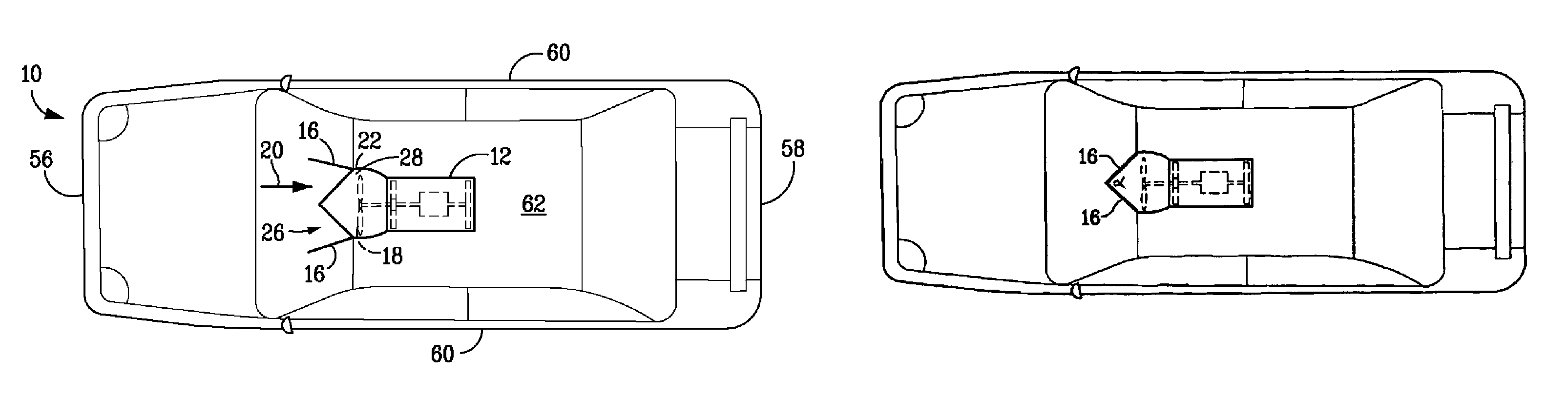
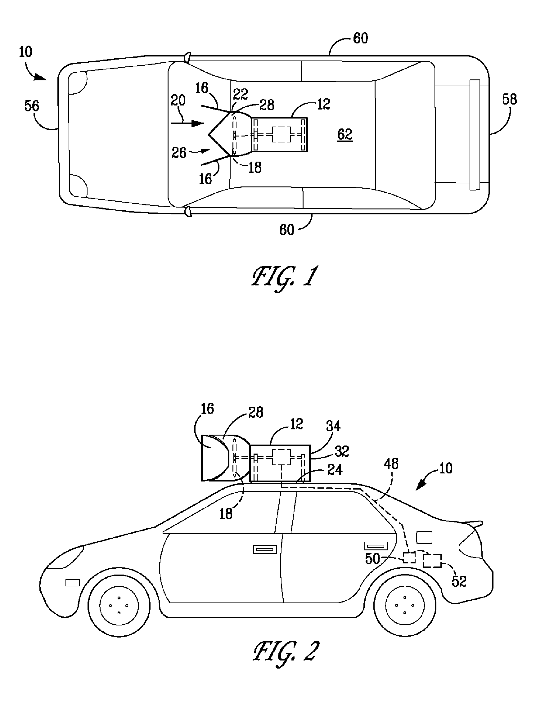
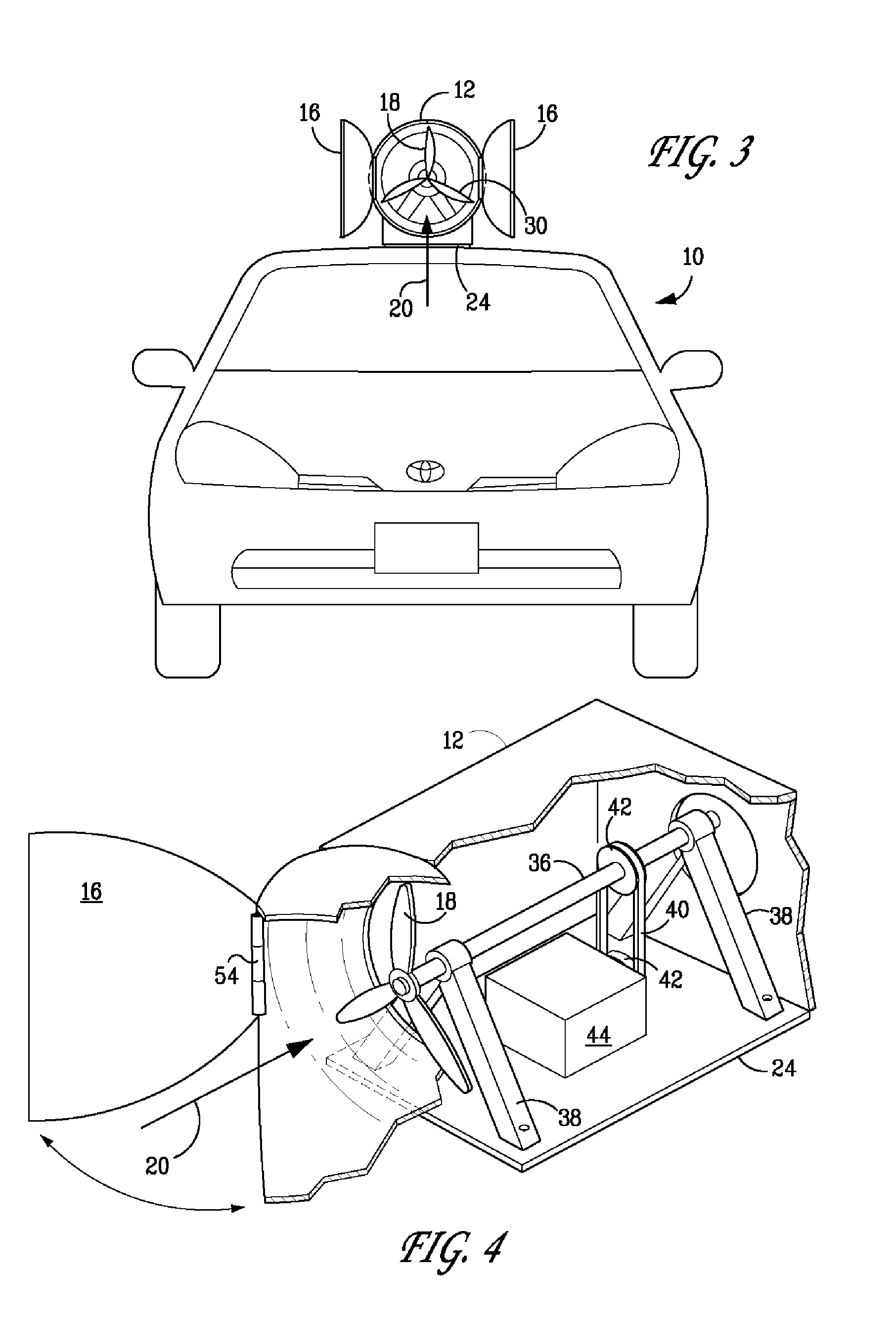
[0020]According to one embodiment of the present invention, FIG. 1 shows a top view of electrically-powered vehicle 10 having a front 56, rear 58, opposing longitudinal sides 60 and roof 62. A controllable shrouded enclosure 12 is mounted to vehicle roof 62 using base plate 24 (FIG. 4). Controllable shrouds 16 are hingedly mounted to shrouded enclosure front end 22 to channel air to turbine 18. As used herein, the term turbine refers to all known wind driven devices, for example, propellers, windmills and the like. FIG. 2 shows a side view and FIG. 3 shows a front view of controllable shrouded enclosure 12 mounted to vehicle 10.

[0021]Referring to FIGS. 1–3, controllable shrouded enclosure 12 has air intake 20 disposed longitudinally to vehicle 10. Controllable shrouded enclosure 12 is optionally sealed from the outside air. Air intake 20 is formed by open shrouds 16. As vehicle 10 moves in a forward direction, air or wind enters air intake 20. Optionally, but preferably, shrouds 16 ...


PUM


Abstract

A shrouded enclosure is mounted to a vehicle roof, the shrouded enclosure comprising an air intake formed by controllable shrouds, a turbine, an electricity generating device, and a discharge outlet. The turbine is interposed between the air intake and the discharge outlet, operatively connected to the electricity generating device and adapted to operate by the air passing through the shrouded enclosure when the vehicle is in motion. The turbine rotates about a turbine shaft mounted on a pair of bearing towers. The rotational energy of the turbine shaft is transferred to the electricity generating device. A base plate is interposed between the shrouded enclosure and the mounting surface of the vehicle. An electrical circuit provides electrical continuity between the electricity generating device and the battery during predetermined periods thereby generating electrical energy to charge the battery with the generated electrical energy. The controllable shrouds are opened to a predetermined position during the predetermined periods of electrical continuity and are otherwise closed to form a predetermined aerodynamic shape to reduce drag during vehicle movement.

Description

FIELD OF THE INVENTION[0001]This invention relates generally to an electrically powered vehicle and more particularly to a system for charging an electrically powered vehicle battery utilizing a controllable shrouded wind-operated turbine and an electricity generating device for charging the batteries while the vehicle is in motion.BACKGROUND OF THE INVENTION[0002]Increasing use of gasoline-powered vehicles significantly contributes to environmental pollution, noise and depletion of crude oil reserves. Electrically-powered vehicles are known to solve some of the problems associated with gasoline-powered vehicles, but such vehicles are not yet in widespread use. Electrically-powered vehicles have certain drawbacks as compared to vehicles powered by conventional gasoline engines and newer hybrid vehicles.[0003]Significant drawbacks include limited travel range between battery recharging and excessive time required for recharging the batteries. The average travel distance between batte...

Claims


Application Information

Patent Timeline
IPC IPC(8): F03D9/00H02P9/04
CPCB60K16/00F03D9/002F03D11/04B60L8/006B60K2016/006F05B2240/13F05B2240/941Y02E10/725Y02E10/728Y02T10/7083Y02T10/90F03D13/20F03D9/25F03D9/32F03D1/04Y02E10/72Y02T10/7072
Inventor DEETS, EDWARD
Owner DEETS EDWARD
Why Eureka
Try Eureka