Electronic transformer/inductor devices and methods for making same

a technology of electric transformers and inductances, applied in the direction of transformers/inductances, fixed transformers, magnetic cores of transformers/inductances, etc., can solve the problem of windings not being insulated by electric wires, and achieve the effects of improving magnetic performance, simplifying electrical connections, and superior heat removal

Inactive Publication Date: 2006-11-14
MULTI FINELINE ELECTRONIX INC
View PDF55 Cites 31 Cited by
  • Summary
  • Abstract
  • Description
  • Claims
  • Application Information

AI Technical Summary

Benefits of technology

[0007]The embodiments of the present invention provide inductors and transformers and methods of manufacturing these devices which offer advantages over the state-of-the-art. These inductors and transformers connected in accordance with this invention have a number of applications in the electronics, telecommunication and computer fields. In one embodiment described below, a rectangular slab of ferromagnetic material is encapsulated between printed circuitry. A plurality of through holes (vias) are drilled through or formed during manufacture of the slab from the top face of the slab to the bottom face of the slab, the number of holes corresponding to the number of desired turns of the windings. This embodiment utilizes Ampere's Law in a very novel manner to form a transformer, inductor, or the like within the circuit board rather than the use or assembly of discrete inductive devices to the circuit board. Thus, the windings are not insulated electric wires. Rather, the holes through the slab are made electrically conductive by through hole plating or the like and electrically connect with the printed circuits encapsulating the slab. This pattern of plated through holes and the printed circuitry form the inductor and transformer windings with the core of the inductors and transformers being the drilled or formed slab of ferromagnetic material. This embodiment provides substantial improvements, particularly in fabricating high frequency inductors and transformers.
[0011]In addition to the advantages described above, the embodiments of the present invention have a number of additional advantages. These include: superior heat removal, outside connections that are more accessible to simplify electrical connection, shorter flux paths to increase magnetic performance, simpler fabrication, interconnections that are more integrated, smaller inductive devices, superior performance, and excellent manufacturing repeatability.

Problems solved by technology

Thus, the windings are not insulated electric wires.

Method used


Image

  • Electronic transformer/inductor devices and methods for making same
  • Electronic transformer/inductor devices and methods for making same
  • Electronic transformer/inductor devices and methods for making same

Examples


Embodiment Construction

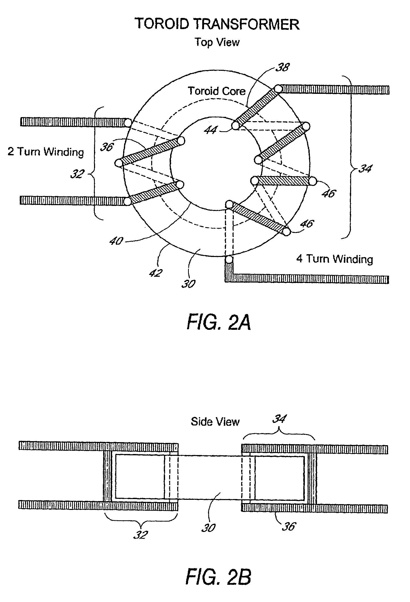
[0053]FIG. 2 illustrates a typical prior art transformer with a toroidal core 30. For simplicity this transformer has two windings of insulated wire: a two-turn winding 32 and a four-turn 34 winding. Each turn 36 encircles the material of the core 30 such that when electrical current is passed through one winding an encircling magnetic flux path 38 flows within the core 30. FIG. 2A illustrates the windings 32, 34 passing through the center of the core 30, and around the outside of the core 30. The windings 32, 34 as shown in FIG. 2 are inductively coupled together by way of the core 30. The core 30 provides a magnetic flux path which couples the first winding 32 to the second winding 34 thereby generating an electrical voltage at the second winding when there is a voltage present at the first.

[0054]Embodiments of the present invention have a very different core and winding arrangement than that shown in FIG. 2. FIG. 3 shows a ferromagnetic slab 10 having a plurality of appropriately...


PUM

PropertyMeasurementUnit
diameteraaaaaaaaaa
diameteraaaaaaaaaa
diameteraaaaaaaaaa

Abstract

The present invention relates to transformer 1 inductor devices and to the methods of construction for inductive components such as inductors, chokes, and transformers. Plural via holes are formed through a ferromagnetic substrate. Primary and secondary conductors are placed through common vias to form a plurality of cell transformers have a 1:1 turns ratio. Circuits connect these primary and secondary winding in parallel and serial combustion to provide a transformer having the desired turns ratio.

Description

PRIORITY CLAIM[0001]This application claims the benefit of U.S. Provisional Application No. 60 / 411,801 filed Sep. 16, 2002 entitled “Electronic Transformer / Inductor Devices and Methods for Making Same.”FIELD OF THE INVENTION[0002]The present invention relates to inductive components and methods for manufacturing these components.BACKGROUND OF THE INVENTION[0003]Inductive components are commonly fabricated using ferromagnetic cores and windings of insulated electrical wire. The ferromagnetic cores are typically toroidal cores, rod cores, or assemblies made of a lower E shaped ferromagnetic part and a ferromagnetic cap connecting the three legs of the E such as shown in FIG. 1.[0004]The toroid and rod cores are manually or automatically wound with the insulated copper wire to form a number of multiple turn windings for a transformer or a single winding for an inductor. The assembly is then typically encapsulated to protect the wires. The circuit connection is made by the solder termin...

Claims


Application Information

Patent Timeline
Patent Type & Authority Patents(United States)
IPC IPC(8): H01F5/00H01F27/28H01F17/00H01F17/06H01F30/00H01F41/04H05K1/16
CPCH01F17/0006H01F17/0033H01F27/2804H01F41/046Y10T29/49073H01F2038/006H05K1/165Y10T29/4902Y10T29/49165H01F2017/002H01F27/24
Inventor HARDING, PHILIP A.
Owner MULTI FINELINE ELECTRONIX INC
Why Eureka
Try Eureka