
Forward error correction apparatus and method in a high-speed data transmission system

a high-speed data transmission and error correction technology, applied in the direction of electrical equipment, code conversion, coding, etc., can solve the problem of inability to realize the algorithm for decoding the turbo code, the probability of undetected error in the codeword in which the error occurred during decoding is relatively high, and the error floor phenomenon may occur at a desired bit error ra

Active Publication Date: 2006-11-14
SAMSUNG ELECTRONICS CO LTD
View PDF4 Cites 51 Cited by
  • Summary
  • Abstract
  • Description
  • Claims
  • Application Information

AI Technical Summary

Benefits of technology

[0043]It is, therefore, an object of the present invention to provide a simple decoding apparatus and method for an error correction code.
[0045]It is further another object of the present invention to provide an LDPC decoding apparatus and method for reducing a calculation amount of each node when a sum-product algorithm is used.
[0046]It is still another object of the present invention to provide an apparatus and method for performing a sum-product algorithm, capable of reducing a calculation amount while maximally maintaining LDPC performance.
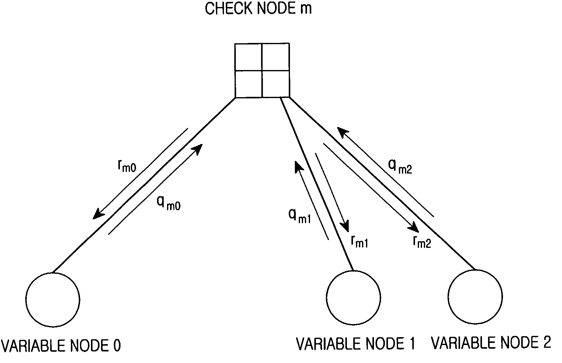
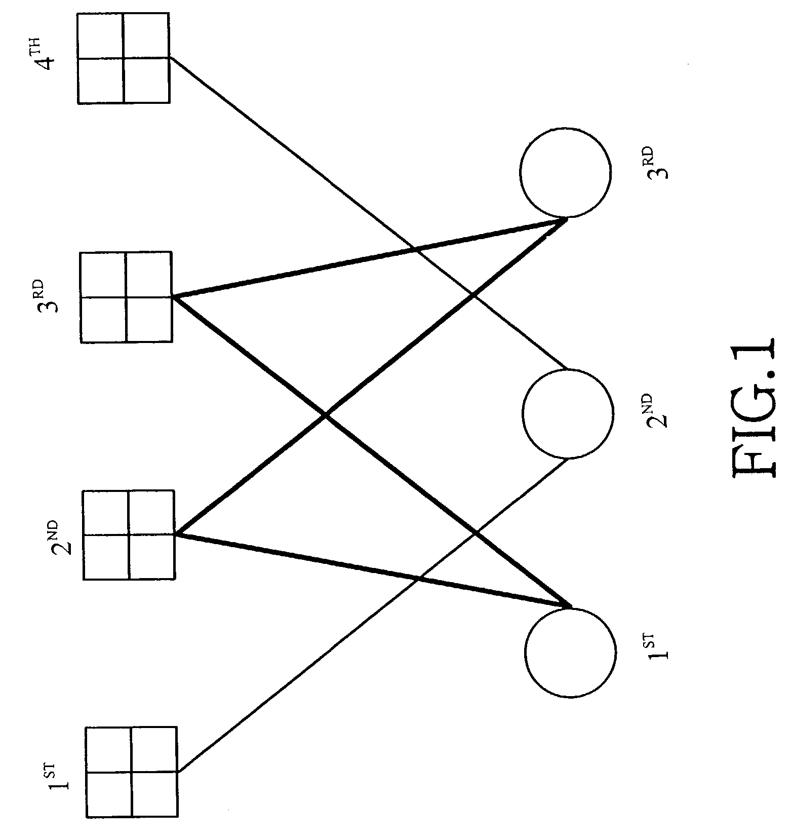
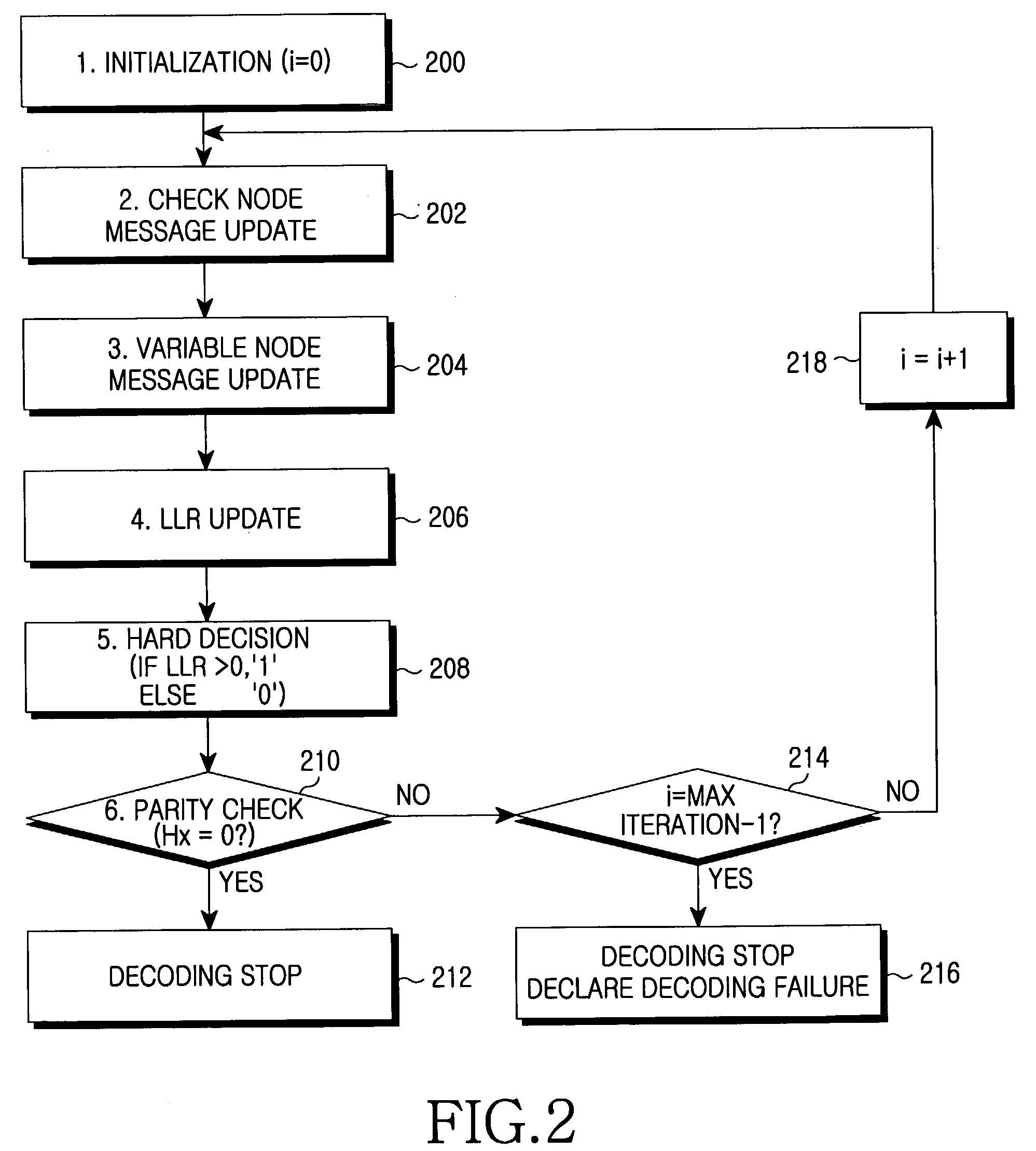
[0047]To achieve the above and other objects, the various embodiments of the invention provide a forward error correction method for decoding coded bits transmitted over a radio channel after being generated by encoding as many binary bits as the number of columns with low density parity check matrixes having rows and the columns. The method comprises the steps of: converting each of the coded bits into a log likelihood ratio (LLR) value indicating a ratio of probability of zero to probability of one, and applying the converted values to as many variable nodes as the number of elements of the row; delivering messages applied to the variable nodes to check nodes connected to the variable nodes; checking a message having a minimum value among the messages delivered from the variable nodes, and determining a sign of the message having the minimum value by calculating the product of signs of other messages except a message of a variable node that is to transmit the checked message; receiving, by the variable nodes, messages updated in the check nodes, adding up signs of the received messages and a sign of an initial message, applying a weighting factor of 1 when the signs are all identical, and when the signs are not all identical, updating a message of a variable node by applying a weighting factor having a predetermined value smaller than 1 to the sum of messages received from all other check nodes and adding a previous value to the result value; determining the LLR of an initial input value by using the updated value of the variable node; and hard-deciding values of the variable nodes, performing parity check on the hard decision values by using the low density parity code matrixes, and stopping the decoding when no error occurs as a result of the parity check.

Problems solved by technology

Therefore, during decoding of a signal coded with the turbo code, an error floor phenomenon may occur at a desired bit error rate.
In addition, undetected error probability for a codeword in which an error has occurred during decoding is relatively high.
Third, an algorithm for decoding the turbo code cannot be realized in a parallel architecture, so there are limitations in increasing the decoding rate.
Therefore, when the sum-product algorithm is used, a large amount of calculation is required in the decoding process.
Accordingly, the use of the sum-product algorithm undesirably increases hardware complexity.
This increases complexity during hardware implementation due to the complicated calculation of tanh( ) function.
Since such an operation must be performed on all edges in sequence, each check node undesirably requires a relatively large amount of calculation and a long calculation time.

Method used


Image

  • Forward error correction apparatus and method in a high-speed data transmission system
  • Forward error correction apparatus and method in a high-speed data transmission system
  • Forward error correction apparatus and method in a high-speed data transmission system

Examples


Embodiment Construction

[0064]Several embodiments of the present invention will now be described in detail with reference to the annexed drawings. In the drawings, the same or similar elements are denoted by the same reference numerals even though they are depicted in different drawings. In the following description, a detailed description of known functions and configurations incorporated herein has been omitted for conciseness.

[0065]The embodiments of the present invention modifies a sum-product algorithm used for LDPC code decoding. In the following description, a decoding algorithm for an LDPC code according to the embodiments of the present invention will be referred to as “modified sum-product algorithm.”

[0066]In the modified sum-product algorithm according to the embodiments of the present invention, the check node message update process of Equation (2), described in conjunction with the prior art, is modified into

[0067]rmn(j)≈(∏i=1dc-1⁢sgn(qi))⁢mini|qi|,i=1,2,⁢…⁢,dc-1Equation⁢⁢(7)

[0068]Equation (7)...


PUM


Abstract

A forward error correction method for decoding coded bits generated by low density parity check matrixes. The method comprises converting each of the coded bits into a log likelihood ratio (LLR) value, and applying the converted values to variable nodes; delivering messages applied to the variable nodes to check nodes; checking a message having a minimum value among the messages, and determining a sign of the message having the minimum value; receiving messages updated in the check nodes, adding up signs of the received messages and a sign of an initial message, applying a weighting factor of 1 when all signs are identical, and when all signs are not identical, updating a message of a variable node by applying a weighting factor; determining LLR of an initial input value; and hard-deciding values of the variable nodes, performing parity check on the hard decision values, and stopping the decoding when no error occurs.

Description

PRIORITY[0001]This application claims priority under 35 U.S.C. § 119 to an application entitled “Forward Error Correction Apparatus and Method in a High-Speed Data Transmission System” filed in the Korean Intellectual Property Office on Jun. 11, 2002 and assigned Serial No. 2002-32690, the contents of which are incorporated herein by reference.BACKGROUND OF THE INVENTION[0002]1. Field of the Invention[0003]The present invention relates generally to a forward error correction apparatus and method in a digital communication system, and in particular, to a forward error correction apparatus and method in a digital communication system for high-speed data transmission.[0004]2. Description of the Related Art[0005]Generally, in a digital communication system, errors occur due to the noise generated in a transmission link, and various error correction techniques are used to correct the errors. In a wireless communication system adopting the 3GPP (3rd Generation Partnership Project) or 3GPP...

Claims


Application Information

Patent Timeline
IPC IPC(8): H03M13/03H03M13/00H04B7/005H03M13/11
CPCH03M13/1111H03M13/1117H03M13/112H03M13/658H04B7/005
Inventor YU, NAM-YULKIM, MIN-GOO
Owner SAMSUNG ELECTRONICS CO LTD
Learn More