
Apparatus with multi-directional radiation emitters for printing a dye image onto a three dimensional object

a dye image and multi-directional radiation technology, applied in the field of dye image application, can solve the problems of poor quality transfer image, general unacceptable results when applied to three-dimensional objects, and lack of flexibility necessary to mold to the required three-dimensional shapes, and achieve the effect of optimal heating efficiency

Inactive Publication Date: 2006-11-21
KII TEKU INC
View PDF12 Cites 48 Cited by
  • Summary
  • Abstract
  • Description
  • Claims
  • Application Information

AI Technical Summary

Benefits of technology

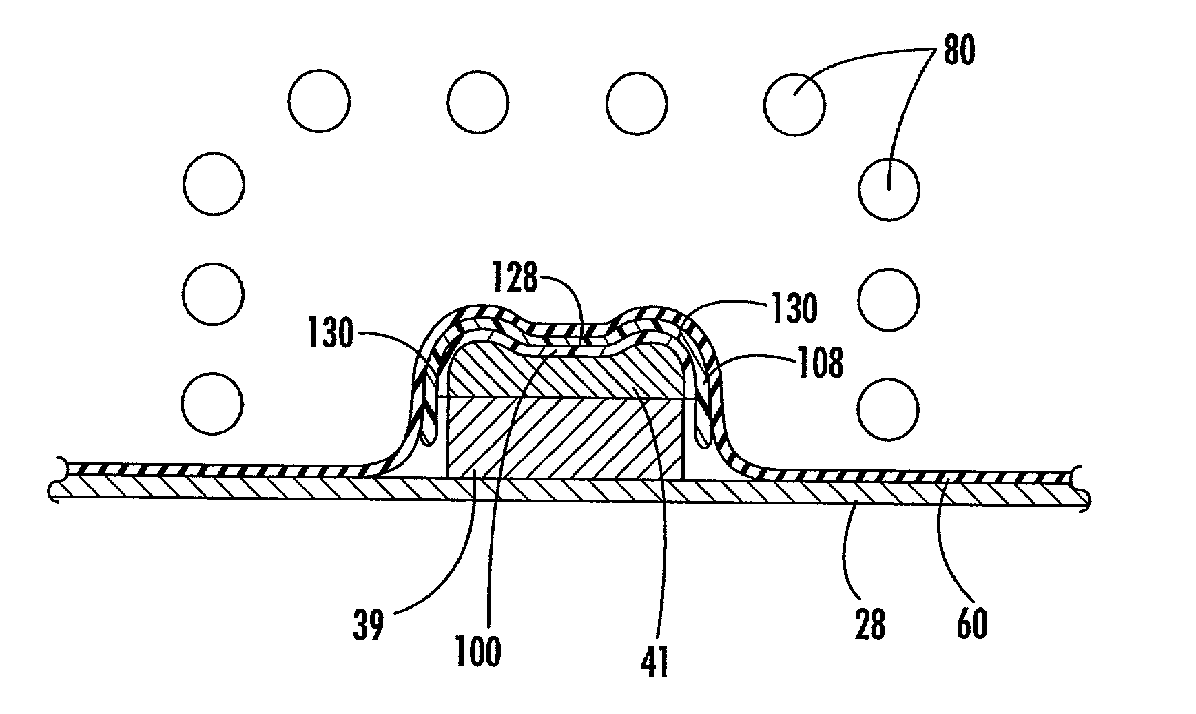
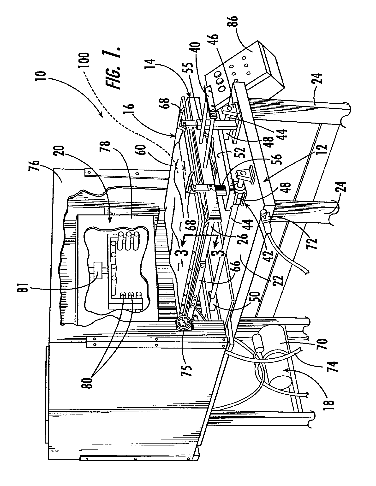
[0006]The apparatus and method of the present invention is operable for carrying out the effective transfer of a dye image from a transfer carrier sheet to a three dimensional object while overcoming the poor quality transfer seen in the prior art. The apparatus of the present invention generally includes a bed assembly having a surface with a fixture mounted thereon for receiving an object having plastic outer surfaces to be printed, a dye bearing flexible transfer carrier sheet that is positioned over the object to be printed, a flexible membrane that is positionable over the dye bearing sheet, the object and a portion of the bed assembly surface, a vacuum means for drawing the membrane into pressurized communication with the carrier sheet to effect the pressurized engagement thereof with the object to be printed, and means for selectably heating the sheet with the dye thereon, the object, the membrane, and optionally preheating the carrier sheet thereby improving its flexibility and to transfer the dye to the object to produce the desired image thereon. In the preferred embodiment of the apparatus of the instant invention, the heating means comprises one or a plurality of radiant heating elements which emit radiant heat, preferably primarily in the infrared wavelength range, to effect heating of the flexible membrane, the carrier sheet, the dye and the object to which the dye image is to be applied. In addition, the radiant heating means is constructed so that it emits radiation towards the bed assembly surface from various angles whereby a three-dimensional member on the bed assembly surface can be heated uniformly. In this regard, preferably the radiant heating means comprises infrared radiation emitter tubes in an inverted U-shaped configuration. Additionally, a reflector array directs radiation from the emitter towards surfaces of the object that do not directly receive radiation such as the ends of the cell phone cover. Also, in the preferred embodiment, the flexible membrane is preferably matched with the radiant heating means so that it is specifically absorptive to radiation within the wavelength range emitted therefrom to achieve optimum heating efficiency.
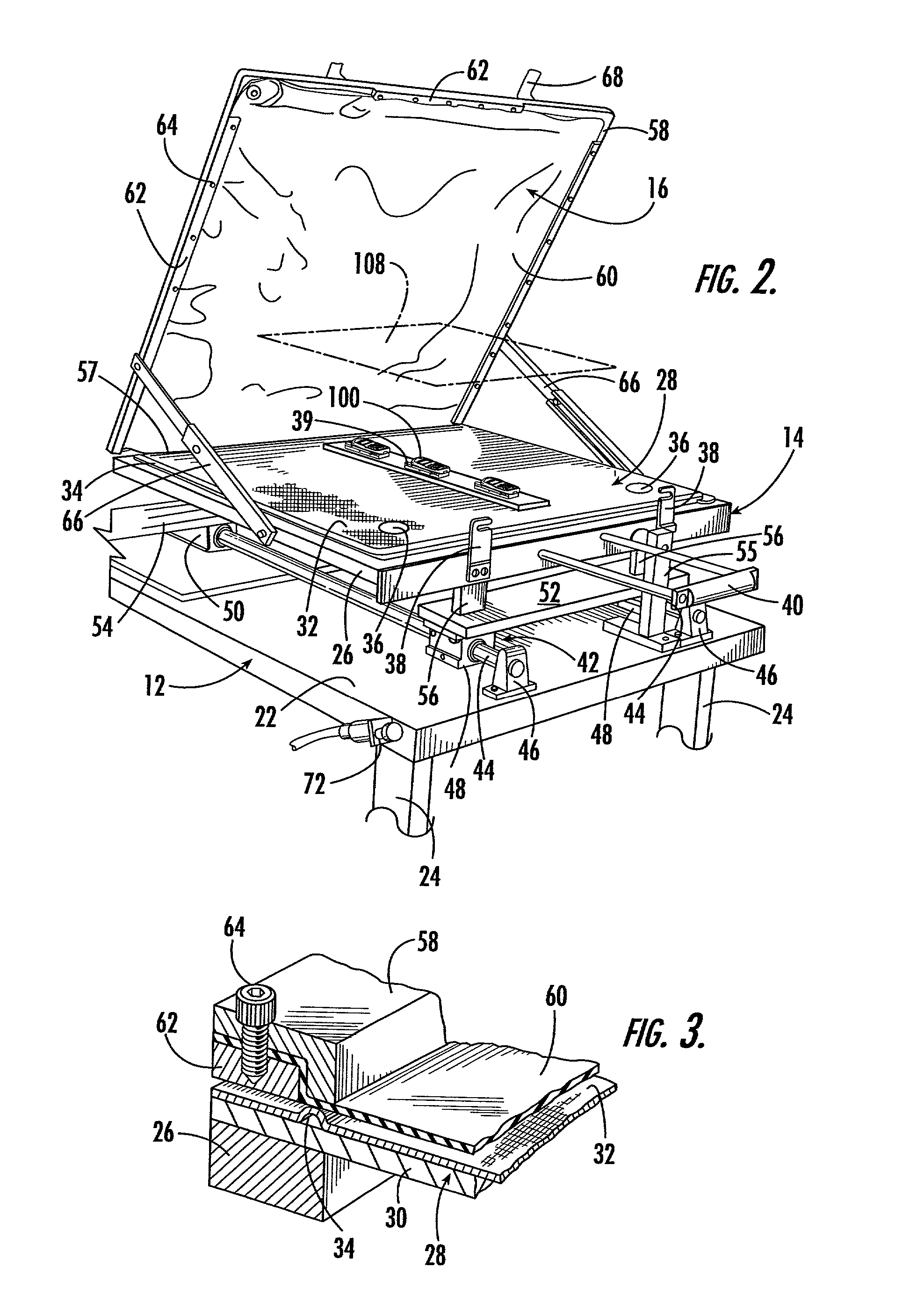
[0008]One particular use for the apparatus of the instant invention is in the application of dye transfer images to the interchangeable outer covers for cellular telephones. Specifically, the apparatus of the present invention can be constructed so that it is adapted to receive an array of several cellular telephone covers and simultaneously apply dye images to the array of covers in a batch fashion. In this regard, when the apparatus of the instant invention is constructed for cellular telephone covers, it further includes an array of receiver dies installed on the bed assembly surface, whereby each die receives a single cell phone cover and maintains the cover in substantially stationary relation on the bed while the carrier sheet is placed in registration over the cell phone cover and the desired images are applied thereto. A single sheet or a sheet having a plurality of dye images thereon, which are in the mirror images of the desired images, is overlaid on the cell phone covers so that the images are in the desired orientation thereon. In the preferred embodiment, a plurality of registration pins are provided on the frame, and a plurality of apertures are provided in the sheet for receiving the registration pins to assure proper registration of the sheet relative to the array of cell phone covers residing on the bed. The carrier sheet is sufficiently flexible to allow the sheet to be drawn onto and around the contours of the cell phone covers so as to simultaneously contact both the top surfaces and side surfaces of the covers allowing an image to be applied to all of the covers in a three dimensional fashion. The dye carrier sheets are placed over the covers as described above, the membrane is placed over the bed and covers, then the membrane is evacuated of air so that it is drawn into pressurized communication with the covers, and heat is applied. An additional step that includes preheating the carrier sheets may be included before evacuating the membrane to improve the flexibility of the carrier sheet to allow it to be drawn into closer contact with the covers when the membrane is evacuated.

Problems solved by technology

While this process is generally well known in the prior art, it produces generally unacceptable results when applied to three-dimensional objects.
However, when an image is applied using the two dimensional printing technique of the prior art, the image can easily be applied to the front surface of the object, but when the carrier sheet is bent around the contours of the cover it tends to gather and crease resulting in a poor quality transfer image.
The drawback in the current technology is that while the paper carrier worked well for flat two-dimensional objects, it does not provide a great degree of flexibility necessary to mold to the required three-dimensional shapes.
This arrangement results in uneven and often wrinkled image transfer, as the paper does not firmly and uniformly contact the substrate object as the carrier sheet will bunch and gather at the corners and edges of the object.
Further, because of the relative lack of flexibility exhibited by the carrier sheets, it makes the simultaneous application and transfer of a dye image from a carrier sheet to the top and sides of a three-dimensional object very difficult.
In addition, another drawback to the prior art technique is that the infrared heating array used to effect the transfer consists of a flat array of infrared heat lamps.
This configuration creates further problems when transferring images onto three dimensional objects because it does not provide uniform heating along the top and sides of the three dimensional object resulting in uneven image transfer along the sides of the object.

Method used


Image

  • Apparatus with multi-directional radiation emitters for printing a dye image onto a three dimensional object
  • Apparatus with multi-directional radiation emitters for printing a dye image onto a three dimensional object
  • Apparatus with multi-directional radiation emitters for printing a dye image onto a three dimensional object

Examples


Embodiment Construction

[0021]Referring now to the drawings, the apparatus of the instant invention is illustrated and generally indicated at 10 in FIG. 1. The apparatus 10 is operable for applying dye images to three dimensional objects, particularly objects with plastic outer surfaces, in accordance with processes of the type wherein a flexible sheet bearing a transfer dye in the mirror of a desired image, known as a carrier sheet, is overlaid on the object and the image is transferred to the object through the application of heat to the dye while the carrier sheet is maintained in pressurized engagement with the object. The apparatus 10 generally comprises a base 12, a bed assembly 14, a flexible membrane assembly 16 that is positionable in overlying relation on the bed assembly 14, a vacuum assembly 18 and a radiant heating assembly 20. The vacuum assembly 18 is in fluid communication with the bed assembly and is operable for evacuating the area between the membrane assembly 16 and the bed assembly 14 ...


PUM

PropertyMeasurementUnit
flexibleaaaaaaaaaa
angleaaaaaaaaaa
distanceaaaaaaaaaa

Abstract

The present invention provides an apparatus and method for applying preselected dye images to three dimensional objects, having plastic outer surfaces, utilizing flexible carrier sheets bearing dyes in the mirror images of the preselected images, where the sheets are overlaid in registration with the objects and maintained in pressurized engagement therewith while the sheets and the objects are heated. The present invention includes a bed for receiving at least one three-dimensional object member thereon with a flexible dye bearing carrier sheet placed in registration on the object and a resiliently flexible membrane, which is positionable over the sheet on the member. A vacuum assembly of the apparatus is operable to evacuate the area between the membrane and the bed in order to draw the membrane into pressurized engagement with the flexible sheet on the member thereby drawing the flexible sheet around the various surfaces of the three dimensional object. Radiant heating elements are operable both to preheat the carrier sheet, improving its flexibility and to heat the membrane after the vacuum assembly has been actuated, whereby the dye on the sheet is applied to the surfaces of the object to produce the preselected image thereon.

Description

PRIORITY CLAIM TO EARLIER FILED APPLICATION[0001]This application claims priority to earlier filed Provisional Application No. 60 / 275,877, filed Mar. 14, 2001.BACKGROUND OF THE INVENTION[0002]The instant invention relates to the application of dye images to various types of three dimensional objects, and more particularly to an apparatus and method for applying dye images to three dimensional objects utilizing a sheet or sheets bearing dyes in the mirror images of the desired images, wherein the dyes are of the type which require heat for the application thereof.[0003]Processes for applying disperse dye images to various types of members, wherein dyes are transferred from carrier sheets bearing the dyes in the mirror images of the desired images, are generally known in the printing art. Other processes that are generally related to the art of the present invention are also generally known in the dye sublimation printing field. In general, processes of this type are carried out by fi...

Claims


Application Information

Patent Timeline
Patent Type & Authority Patents(United States)
IPC IPC(8): B32B37/00B41F16/00B41M5/035B44C1/17
CPCB41F16/00B44C1/1712B41M5/0358Y10T156/1705B32B37/00
Inventor NERI, KENNETHMUTTER, RUDOLPH
Owner KII TEKU INC
Learn More