Composite tensioning members and method for manufacturing same

Inactive Publication Date: 2006-11-21
AIRLOG ACQUISITION CORP
View PDF39 Cites 40 Cited by
  • Summary
  • Abstract
  • Description
  • Claims
  • Application Information

AI Technical Summary

Benefits of technology

[0015]The invention further provides a method of manufacturing long lengths of composite tension members having equalized tension on each composite rod in the bundle of rods.
[0016]A composite tension member of the invention can have a tensile strength that is twice that of conventional stainless steel cable or rod at about one-fourth the weight or with less profile. Reducing the rigging weight for a sailboat, for example, allows less keel weight to be used to offset for the weigh

Problems solved by technology

Although stainless steel cable and stainless steel rod are relatively strong, they suffer from various drawbacks.
First, stainless steel, while strong, is still relatively heavy.
Also, stainless steel cable and rod are subject to stretching (either elastic or permanent deformation).
Furthermore, there are often situations where the stainless steel cable or rod do not extend along completely straight runs, and must bend at certain points.
These bends create localized areas of weakness.
In these cases, the cables and rods are weakened where they pass around the end of the spreaders, thereby compromising the strength of the continuous upper shrouds.
Other problems with stainless steel rigging are corrosion and work hardening.
However, wire rope experiences “permanent stretch” which is caused by settling of the wires in the rope or strand as an initial load is applied.
However, when the shift was made to stainless steel rod rigging there were numerous failures.
First, dew and salt water would get down into the te

Method used


Image

  • Composite tensioning members and method for manufacturing same
  • Composite tensioning members and method for manufacturing same
  • Composite tensioning members and method for manufacturing same

Examples


Embodiment Construction

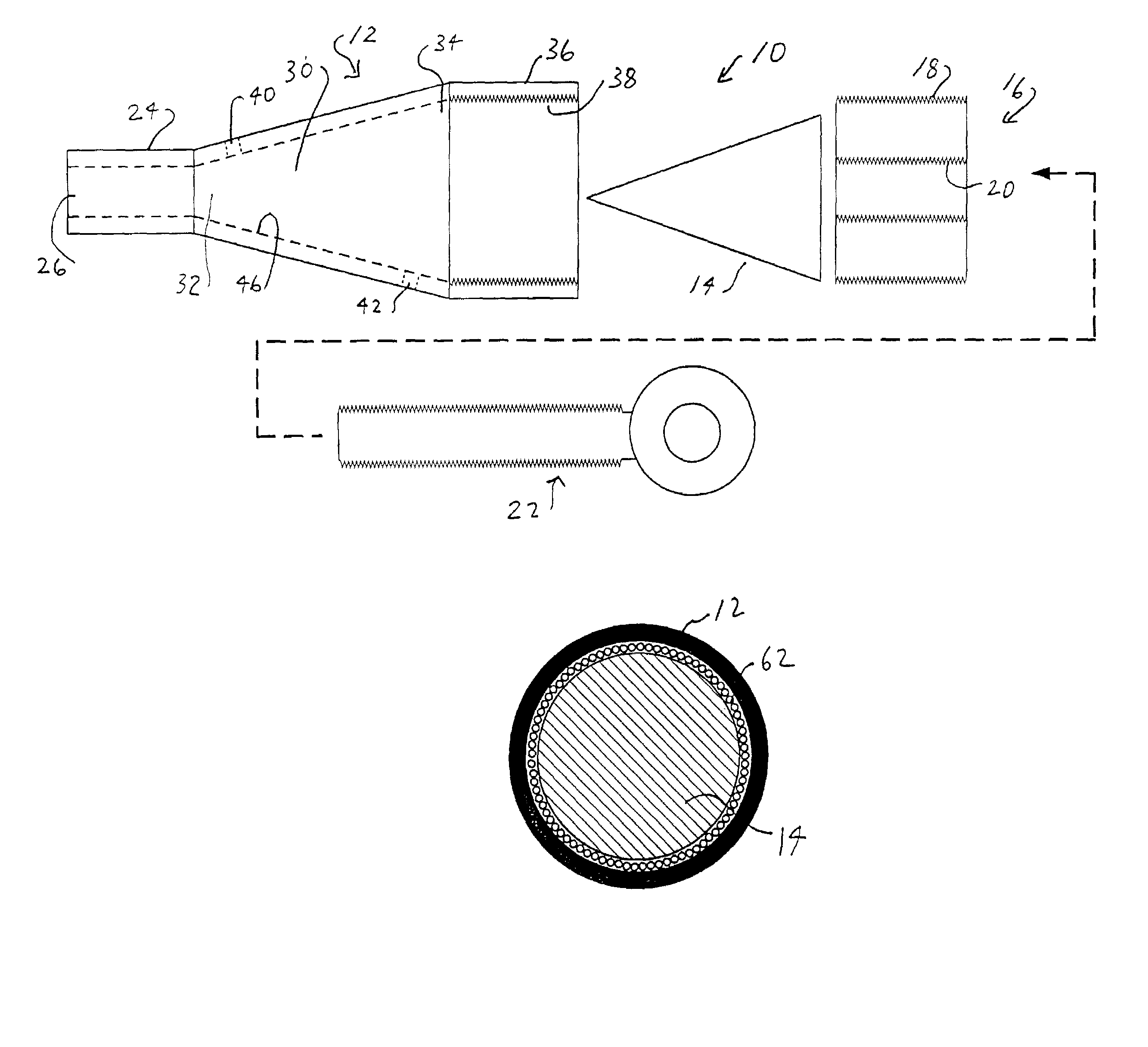
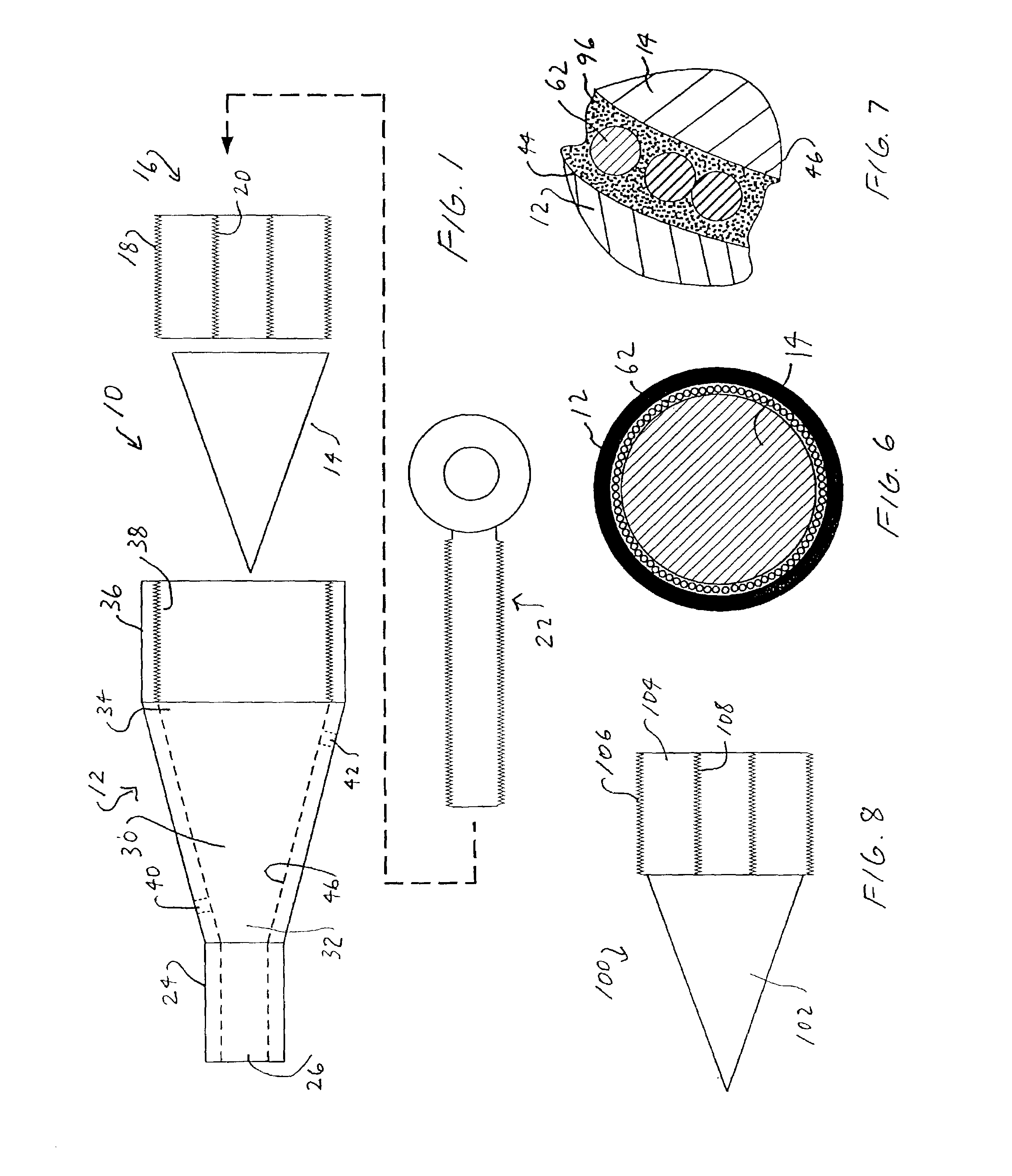
[0045]Turning to FIG. 1, there is shown an exploded view of the termination fitting end 10 which comprises a termination fitting body 12, a deflecting or splaying means, such as a cone insert 14, and a means to secure the cone insert 14, such as a closeout collar nut. Closeout collar nut 16 has external threads 18 and an internally threaded hole 20. A threaded eyehook portion 22 of a turnbuckle portion is sized and threaded to be threadably engagable with internal threads 20 of the closeout collar nut. Cone insert 14 is preferably constructed of a strong and rigid material such as stainless steel, aluminum, titanium, and some other strong material. Termination fitting body 12 has a proximal end 24 with an axial bore 26 formed therethrough. An intermediate portion 28 of termination fitting has a flared interior cavity 30 which flares outwardly from its proximal end 32 to its distal end 34 to define a frusto-conical shaped cavity. Termination housing has a distal end 36 which has atta...


PUM

PropertyMeasurementUnit
Angleaaaaaaaaaa
Forceaaaaaaaaaa
Strengthaaaaaaaaaa

Abstract

A composite tension member. The composite tension member is assembled from a number of composite rods, each having two ends. A wedge plug is formed around the ends of the composite rods. The wedge plugs are inserted into termination fitting having a termination fitting body with an aperture at a proximal end for receipt of the bundle of composite rods and having an internal cavity that flares outwardly from a proximal end to a distal end to closely receive the wedge plug with the composite rods imbedded therein. A closeout nut is used to retain the wedge plug in the termination fitting body. The invention further provides method of manufacturing composite tension members.

Description

[0001]This application claims priority pursuant to 35 U.S.C. §119(e) and 37 CFR §1.78(a)(4), to provisional Application No. 60 / 305,931, filed Jul. 16, 2001.BACKGROUND OF THE INVENTION[0002]A composite tension member and method for manufacturing same, and more particularly a composite tension member formed of a plurality of parallel composite fiber rods bundled together in an intermediate composite cable portion with the rods either splayed out into termination fittings by a cone and attached thereto with adhesives and by friction forces, or imbedded in a wedge or frustum plug, which wedge or plug is fitted into a termination fitting.[0003]There are a variety of applications which require strong yet lightweight tension members, such as standing rigging members for sailboats, industrial structure bracing, lifting cables, mooring cables for offshore drilling platforms, and bridge tendons, to name a few.[0004]Particularly in performance-sensitive areas such as competitive sailboat racin...

Claims


Application Information

Patent Timeline
IPC IPC(8): B21F9/00B32B1/08B66C1/12F16G11/00F16G11/04F16G11/05F16G11/12
CPCB32B1/08B66C1/12F16G11/00F16G11/05F16G11/12Y10T24/3969Y10T24/3973Y10T403/471Y10T403/44Y10T403/7052F16G11/042B32B27/32B32B7/12B32B2327/18B32B2262/101B32B2262/106B32B2319/00B32B9/007B32B25/20B32B2307/54
Inventor SJOSTEDT, ROBBIE J.
Owner AIRLOG ACQUISITION CORP
Why Eureka
Try Eureka