Three-dimensional stereolithographic apparatus

a three-dimensional stereolithographic and apparatus technology, applied in applications, manufacturing tools, instruments, etc., can solve the problems of reducing productivity, taking a long time to shape materials, and extremely expensive ultraviolet laser devices used as light sources

Active Publication Date: 2006-11-21
TEIJIN SEIKI CO LTD
View PDF12 Cites 5 Cited by
  • Summary
  • Abstract
  • Description
  • Claims
  • Application Information

AI Technical Summary

Benefits of technology

[0020]The inventors made extensive studies to accomplish the aforementioned aims of the invention. As a result, it was found that when the production of a three-dimensionally shaped product involving the irradiation of the surface of a photohardenable resin composition with light through an image drawing mask to sequentially form photohardened resin layers having a predetermined sectional shape pattern is accomplished by a method which comprises irradiating the surface of the photohardened resin composition with light while moving the image drawing mask with any suspension during irradiation with light and changing the mask image (mask pattern) of the image drawing mask according to a predetermined sectional shape pattern to be formed, ...

Problems solved by technology

However, the aforementioned related art method involving the use of spot ultraviolet laser beam utilizes a so-called dot drawing process which comprises irradiating the surface of a photohardenable resin with one spot laser beam which is moving along the surface of the photohardenable resin to form a two-dimensional photohardened pattern and thus is disadvantageous in that it takes much time to shape the material, giving a lowered productivity.
Further, since the ultraviolet laser device used as a light source is extremely expensive, this type of a three-dimensional stereolithographic apparatus is expensive, too.
Further, this method comprises sequentially forming a photohardened portion one row by one row to form a two-dimensional photohardened layer and thus takes much time to shape the material.
Accordingly, this method cannot give a sufficiently high shaping rate and thus leaves something to be desired in productivity.
However, there are no existing liquid crystal masks (liquid c...

Method used


Image

  • Three-dimensional stereolithographic apparatus
  • Three-dimensional stereolithographic apparatus
  • Three-dimensional stereolithographic apparatus

Examples


example 1

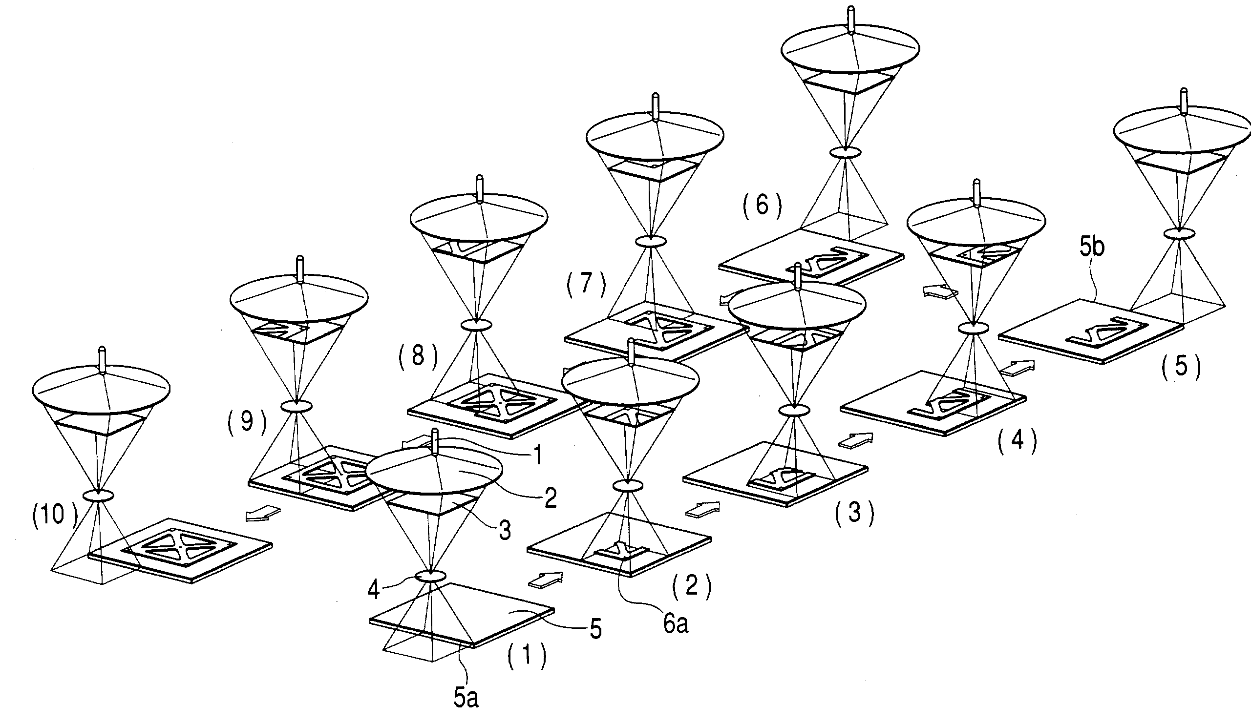
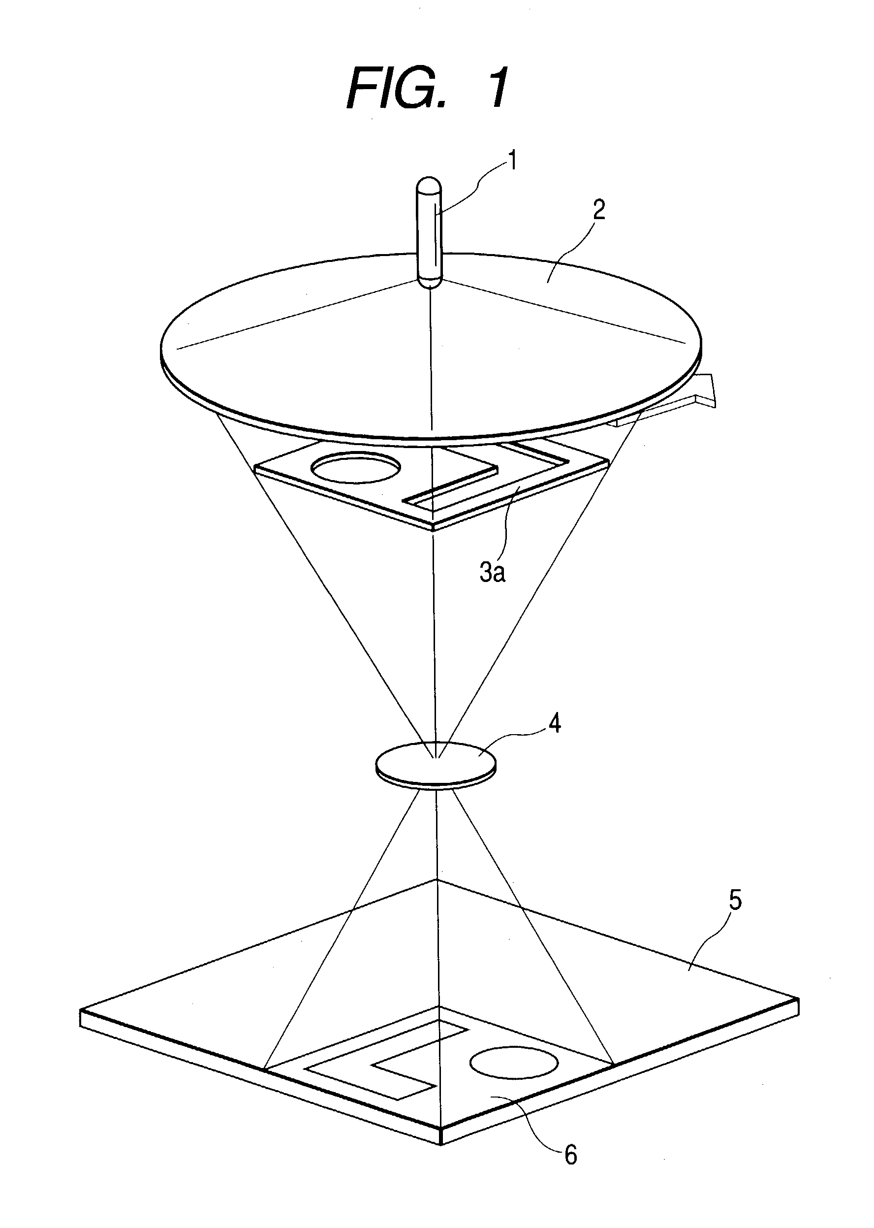
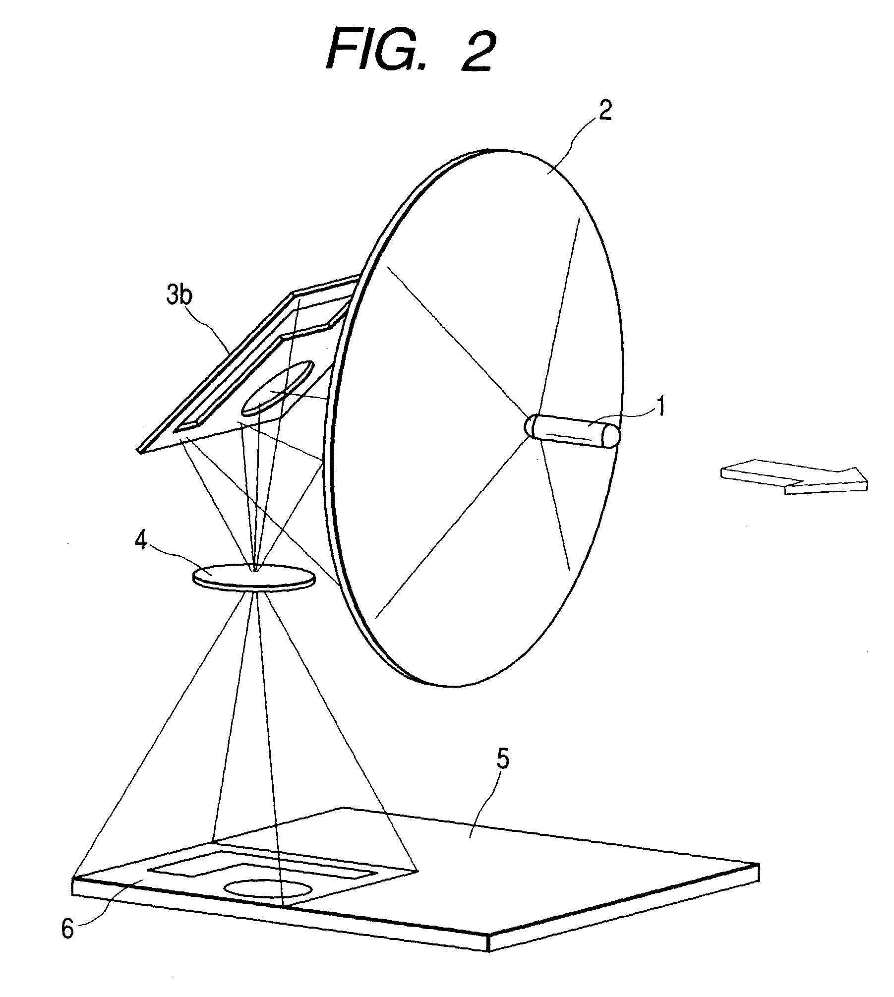
[0100]Using a stereolithographic apparatus shown in FIG. 4 comprising a 150 W metal halide lamp as a light source 1 and a Type system VGA liquid crystal (800×640 pixels) produced by SEIKO EPSON CORPORATION as an image drawing mask 3, a Type ADEKARASCURE HSX-V2 photohardenable resin composition (having a curing sensitivity of 5 mJ) produced by ASAHI DENKA KOGYO K. K. was irradiated with light in such a manner that the projected size on the shaping surface 5 (surface of the photohardenable resin composition) is 35 mm (direction of movement of apparatus)×47 mm (direction perpendicular to the moving direction) (rectangular) and the light energy intensity on the shaping surface 5 is 1 mW / cm2 while the light source 1, the condensing lens 2, the image drawing mask 3 and the projection lens 4 were being integrally moved continuously in parallel to the shaping surface 5 at a velocity of about 7 mm / sec in the forward direction according to the method shown in FIG. 4 with the mask image of the...


PUM

PropertyMeasurementUnit
Areaaaaaaaaaaa

Abstract

A stereolithographic method which comprises irradiating the surface of a photohardenable resin composition with light through an image drawing mask capable of changing its mask image with the image drawing mask being moved in parallel to the surface of the photohardenable resin composition and the mask image of the image drawing mask being changed in synchronism with the movement of the image drawing mask according to the sectional shape pattern on the photohardened resin layer to be formed to form a photohardened resin layer having a predetermined sectional shape pattern and a stereolithographic apparatus therefor.

Description

[0001]The present application is based on Japanese Patent Application No. 2002-66399, the entire contents of which are incorporated herein by reference.BACKGROUND OF THE INVENTION[0002]1. Field of the Invention[0003]The present invention relates to a three-dimensional stereolithographic method and apparatus using a photohardenable resin composition. More particularly, the invention relates to a three-dimensional stereolithographic method and apparatus for producing various three-dimensionally shaped products having a size ranging from small size to large size from a photohardenable resin composition with a high shaping precision and a good productivity at a high shaping rate without causing uneven curing.[0004]2. Related Art[0005]In recent years, a stereolithographic method and apparatus which produces a three-dimensionally shaped product by curing a photohardenable resin according to data inputted in a three-dimensional CAD has been put in practical use. This stereolithographic tec...

Claims


Application Information

Patent Timeline
IPC IPC(8): B28B17/00B29C67/00
CPCB29C67/007B33Y10/00B33Y30/00B29C64/129
Inventor UENO, TAKAKUNI
Owner TEIJIN SEIKI CO LTD
Why Eureka
Try Eureka