Contact carriers (tiles) for populating larger substrates with spring contacts

a technology of contact carriers and substrates, applied in the field of contact carriers, can solve the problems of incomplete coplanarity of terminals of electronic components, requiring extensive rework, and incompleteness of entire components, and achieve the effects of easy rework, easy rework, and convenient mounting

Inactive Publication Date: 2006-11-28
FORMFACTOR INC
View PDF115 Cites 46 Cited by
  • Summary
  • Abstract
  • Description
  • Claims
  • Application Information

AI Technical Summary

Benefits of technology

[0047]An advantage of the present invention is that tiles may be mounted directly to semiconductor devices, including fully-populated C4 dies with active devices, either prior to or after their singulation from a semiconductor wafer. In this manner, spring contact elements are readily mounted to semiconductor devices, while avoiding fabricating the spring contact elements directly upon the semiconductor devices.
[0048]An advantage of the present invention is that the tiles upon which the spring elements are fabricated can be an existing “C4” package having solder bumps on a surface opposite the spring elements. In this manner, the tiles can be mounted to the surface of an electronic component (e.g., space transformer, semiconductor wafer, or the like) by reflow heating.
[0049]An advantage to the technique of using tiles, rather than fabricating spring elements directly upon the surface of the electronic component is that the electronic component is readily re-worked, simply by replacing selected ones of the one or more tiles attached/connected thereto.
[0050]The present invention is applicable to using tiles to populate larger substrates, and the probe element

Problems solved by technology

A subtle problem associated with interconnection elements, including spring contacts, is that, often, the terminals of an electronic component are not perfectly coplanar.
In cases where a large number of such spring elements are required, failure to yield (successfully manufacture) but one of the great many spring elements may result in an entire component being defective (unusable or, a

Method used


Image

  • Contact carriers (tiles) for populating larger substrates with spring contacts
  • Contact carriers (tiles) for populating larger substrates with spring contacts
  • Contact carriers (tiles) for populating larger substrates with spring contacts

Examples


embodiment 200

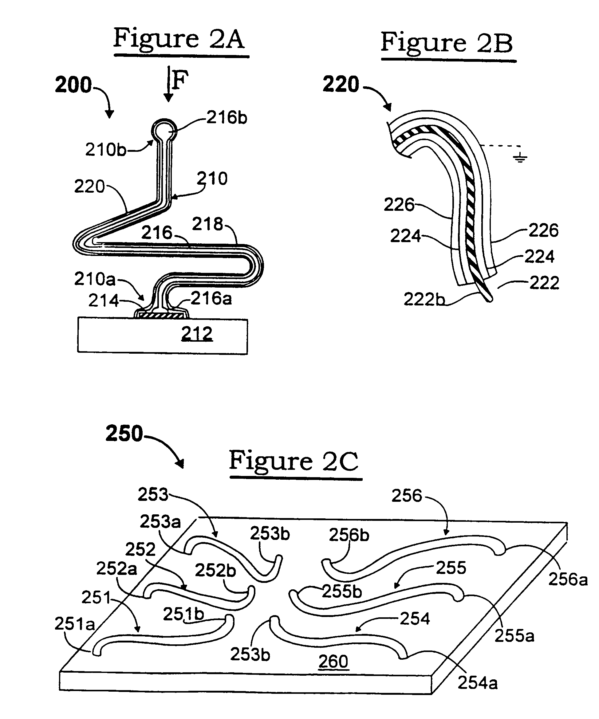
[0151]FIG. 2A illustrates an embodiment 200 of an interconnection element 210 mounted to a terminal 214 of an electronic component 212. In this example, a soft (e.g., gold) wire core 216 is bonded (attached) at one end 216a to the terminal 214, is configured to extend from the terminal and have a spring shape (compare the shape shown in FIG. 1B), and is severed to have a free end 216b. Bonding, shaping and severing a wire in this manner is accomplished using wirebonding equipment. The bond at the end 216a of the core covers only a relatively small portion of the exposed surface of the terminal 214.

[0152]A shell (overcoat) is disposed over the wire core 216 which, in this example, is shown as being multi-layered, having an inner layer 218 and an outer layer 220, both of which layers may suitably be applied by plating processes. One or more layers of the multi-layer shell is (are) formed of a hard material (such as nickel and its alloys) to impart a desired resiliency to the interconn...

embodiment 250

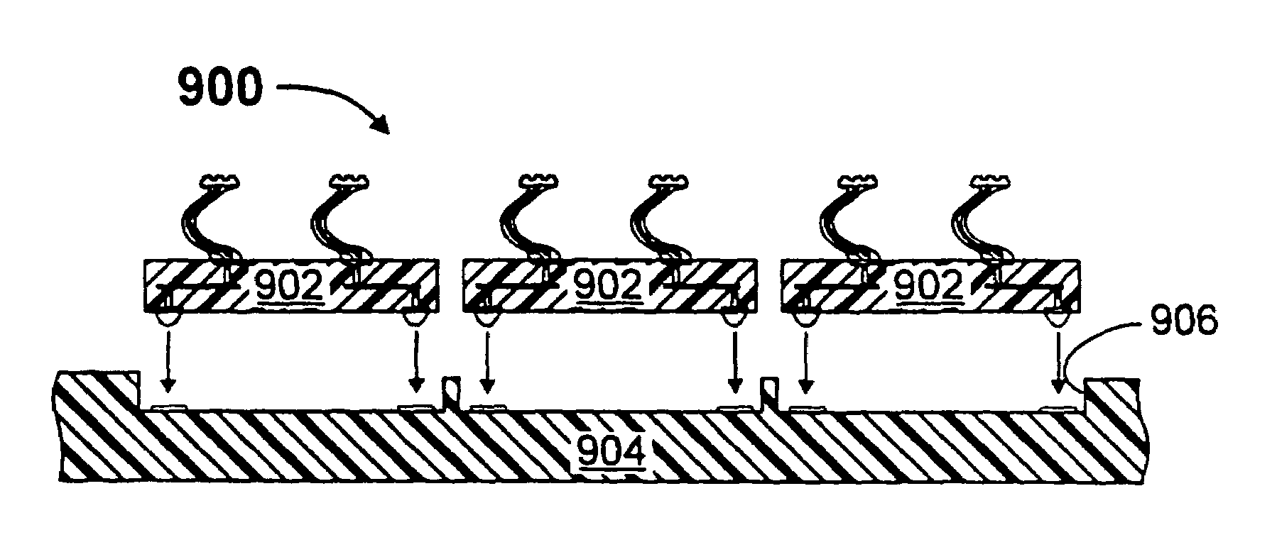
[0168]FIG. 2C illustrates an embodiment 250 wherein a plurality (six of many shown) of interconnection elements 251 . . . 256 are mounted on a surface of an electronic component 260, such as a probe card insert (a subassembly mounted in a conventional manner to a probe card). Terminals and conductive traces of the probe card insert are omitted from this view, for illustrative clarity. The attached ends 251a . . . 256a of the interconnection elements 251 . . . 256 originate at a first pitch (spacing), such as 0.05–0.10 inches. The interconnection elements 251 . . . 256 are shaped and / or oriented so that their free ends (tips) are at a second, finer pitch, such as 0.005–0.010 inches. An interconnect assembly which makes interconnections from a one pitch to another pitch is typically referred to as a “space transformer”.

[0169]As illustrated, the tips 251b . . . 256b of the interconnection elements are arranged in two parallel rows, such as for making contact to (for testing and / or burn...

embodiment 270

[0184]FIG. 2I illustrates an alternate embodiment 270 for fabricating interconnection elements. In this embodiment, a masking material 272 is applied to the surface of a sacrificial substrate 274, and is patterned to have a plurality (one of many shown) of openings 276, in a manner similar to the technique described hereinabove with respect to FIG. 2D. The openings 276 define areas whereat interconnection elements will be fabricated as free-standing structures. (As used throughout the descriptions set forth herein, an interconnection element is “free-standing” when is has a one end bonded to a terminal of an electronic component or to an area of a sacrificial substrate, and the opposite end of the interconnection element is not bonded to the electronic component or sacrificial substrate.)

[0185]The area within the opening may be textured, in any suitable manner, such as to have one or more depressions, as indicated by the single depression 278 extending into the surface of the sacrif...


PUM

PropertyMeasurementUnit
Yield strengthaaaaaaaaaa

Abstract

An interconnection apparatus and a method of forming an interconnection apparatus. Contact structures are attached to or formed on a first substrate. The first substrate is attached to a second substrate, which is larger than the first substrate. Multiple such first substrates may be attached to the second substrate in order to create an array of contact structures. Each contact structure may be elongate and resilient and may comprise a core that is over coated with a material that imparts desired structural properties to the contact structure.

Description

CROSS-REFERENCE TO RELATED APPLICATIONS[0001]This patent application is a continuation of U.S. patent application Ser. No. 994,799 filed Dec. 19, 1997, which is a continuation of U.S. patent application Ser. No. 08 / 789,147 filed Jan. 24, 1997 (now U.S. Pat. No. 5,806,181), which is a continuation-in-part of U.S. patent application Ser. No. 08 / 452,255 (hereinafter “PARENTCASE”) filed 26 May 1995, which is a continuation-in-part of U.S. patent application Ser. No. 08 / 340,144 filed 15 Nov. 1994 (now U.S. Pat. No. 5,917,707), which is a continuation-in-part of U.S. patent application Ser. No. 08 / 152,812 filed 16 Nov. 1993 (now U.S. Pat. No. 5,476,211, 19 Dec. 1995), all of which are incorporated by reference herein.[0002]U.S. patent application Ser. No. 08 / 789,147 is also a continuation-in-part of the following U.S. patent application Ser. No. 08 / 526,246 filed 21 Sep. 1995 (now abandoned);[0003]Ser. No. 08 / 533,584 filed 18 Oct. 1995 (now U.S. Pat. No. 5,772,451);[0004]Ser. No. 08 / 554,90...

Claims


Application Information

Patent Timeline
IPC IPC(8): G01R31/02B23K1/00B23K20/00C23C18/16C25D5/08C25D5/22C25D7/12C25D21/02G01R1/00G01R1/067G01R1/073G01R31/28H01L21/00H01L21/48H01L21/56H01L21/60H01L21/603H01L21/66H01L23/48H01L23/485H01L23/49H01L23/498H01L25/065H01L25/16H01R43/20H05K1/00H05K1/14H05K3/20H05K3/30H05K3/32H05K3/34H05K3/36H05K3/40
CPCB23K1/0016B23K20/004G01R1/06716G01R1/07342G01R1/07378G01R31/2884H01L21/4853H01L21/4889H01L21/563H01L22/20H01L23/49811H01L24/11H01L24/16H01L24/72H01L24/81H01L25/0652H01L25/16H05K3/308H05K3/326H05K3/3426H05K3/4015B23K2201/40C25D5/08C25D5/22C25D21/02G01R1/06711G01R3/00G01R31/2886H01L24/45H01L2224/1134H01L2224/13099H01L2224/45014H01L2224/45124H01L2224/45144H01L2224/45147H01L2224/4554H01L2224/49109H01L2224/73203H01L2224/81801H01L2224/85201H01L2224/85205H01L2924/01004H01L2924/01005H01L2924/01012H01L2924/01013H01L2924/01014H01L2924/01015H01L2924/01022H01L2924/01027H01L2924/01029H01L2924/01039H01L2924/01042H01L2924/01046H01L2924/01047H01L2924/01049H01L2924/0105H01L2924/01051H01L2924/01057H01L2924/01074H01L2924/01075H01L2924/01078H01L2924/01079H01L2924/01082H01L2924/01322H01L2924/014H01L2924/09701H01L2924/10329H01L2924/14H01L2924/19041H01L2924/19043H01L2924/30107H01L2924/3011H01L2924/3025H05K1/141H05K3/20H05K3/3421H05K3/368H05K2201/068H05K2201/1031H05K2201/10318H05K2201/10757H05K2201/10878H05K2201/10909H05K2201/10946H01L24/49H01L2924/00013H01L2924/01006H01L2924/01019H01L2924/01033H01L2924/01045H01L2924/01028H01L2924/10253H01L2924/00014Y10T29/49126Y10T29/49208Y10T29/49222Y10T29/49004H01L2924/00H01L2224/48H01L2224/45015H01L2924/12042H01L2924/15787B23K2101/40Y02P70/50C25D5/605H01L2924/206
Inventor KHANDROS, IGOR Y.ELDRIDGE, BENJAMIN N.MATHIEU, GAETAN L.DOZIER, II, THOMAS H.SMITH, WILLIAM D.
Owner FORMFACTOR INC
Why Eureka
Try Eureka