Grip element

a technology of gripping and hand-held objects, which is applied in the direction of golf clubs, steering devices, cycle equipments, etc., can solve the problems of increasing size or bulk, increasing material costs, and difficulty in handling thin-walled tubular elements formed from very soft materials, and achieves the effect of increasing the productivity ra

Inactive Publication Date: 2006-11-28
SOC DITE SOC BIC
View PDF23 Cites 25 Cited by
  • Summary
  • Abstract
  • Description
  • Claims
  • Application Information

AI Technical Summary

Benefits of technology

[0011]In one embodiment, the grip element is formed as a tubular element having a longitudinal extent shorter than the longitudinal extent of the hand-held article onto which the grip element is to be provided. In particular, the grip element is preferably configured to be positioned at only a gripping section of the hand-held article and thus need only be long enough to occupy such region. For example, th

Problems solved by technology

However, to permit ready handling of known soft grip elements during manufacture and to facilitate assembly on the hand-held article, such soft grip elements require more material than is really necessary to achieve the desired enhanced comfort, thus increasing size or bulk as well as material costs.
Moreover, insertion of a thick-walled grip element over the gripping section of a hand-held article results in a hand-held article significantly bulkier than would be the case without such grip element.
However, thin-walled tubular elements formed from very soft materials are difficult to handle for various reasons.
For instance, the thin wall easily collapses on itself, requiring additional supporting and manipulating devices to permit insertion over a hand-held article.
Moreover, if the material is so soft that it has a high coefficient of friction, the collapsed walls may stick to each other to a certain degree, further complicating the handling of the tubular element.
In addition, if a grip element is designed to reduce

Method used


Image

  • Grip element
  • Grip element
  • Grip element

Examples


Embodiment Construction

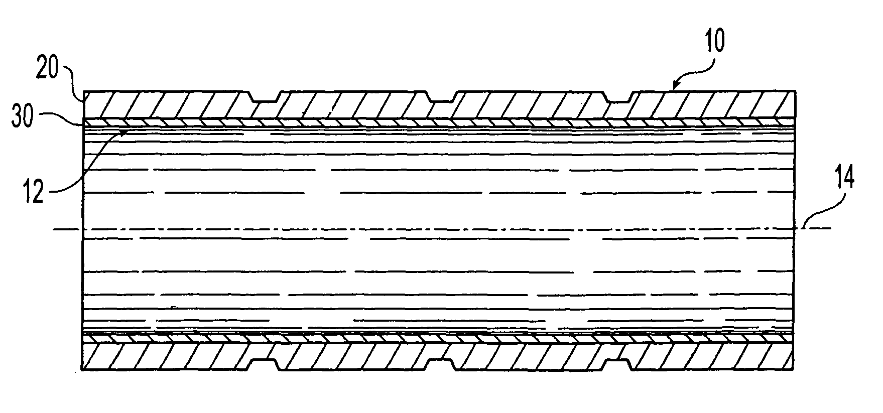
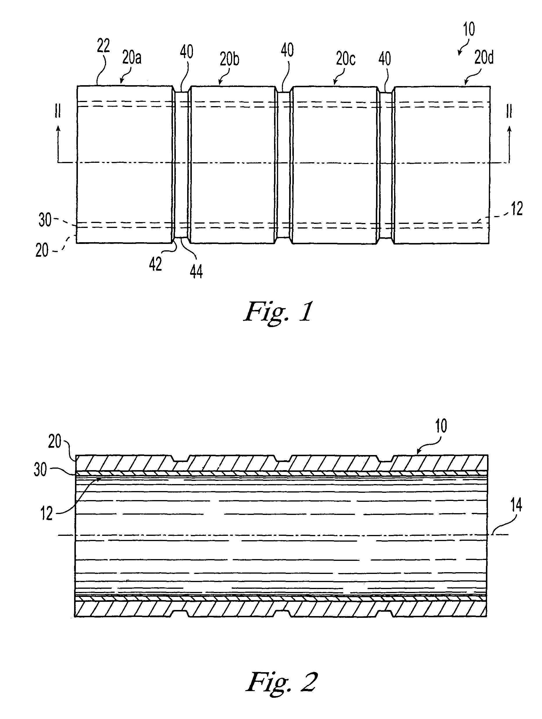
[0019]Referring now to the drawings, an exemplary grip element 10 formed in accordance with the principles of the present invention is illustrated in FIGS. 1 and 2. Grip element 10 is configured to be positioned on a gripping portion of an article. Preferably, grip element 10 is formed with a mounting structure, such as a receiving channel 12 in which a portion of an article is inserted to mount grip element 10 thereon. It is noted that reference herein is made to a “receiving channel” for the sake of convenience, and not with any intent to limit the mounting structure to only a “receiving channel.” For instance, grip element 10 may be inserted over a portion of a hand-held article and advanced until positioned over the gripping portion of the article. If more than one gripping portion is provided on a given hand-held article, then more than one grip element 10 may be provided, a grip element 10 being provided over each gripping portion. Grip element 10 may be positioned over a port...


PUM

PropertyMeasurementUnit
Thicknessaaaaaaaaaa
Diameteraaaaaaaaaa
Compressibilityaaaaaaaaaa

Abstract

A grip element having a soft, compressible and deformable outer layer supported by an underlying support structure sufficiently rigid to maintain a receiving channel of the grip element in an open configuration. The support structure facilitates manipulation of the grip element and assembly of the grip element onto a hand-held article without having the outer layer collapse on itself as would occur without the support structure as a result of the soft, deformable nature of the outer layer. The grip element may be formed separately from the hand-held article on which it is to be assembled, and then positioned thereon such that the hand-held article is sold with the grip element pre-assembled thereon. If desired, the grip element may be provided separate from the hand-held article, the outer layer providing a readily compressible and deformable soft cushioning surface and the support structure facilitating insertion of the outer layer over at least a portion of a hand-held article. The outer layer and support structure may be co-molded such that the materials thereof are permanently and directly bonded together. If desired, a pattern may be formed on the outer layer, such as grooves, dimples, ribs, bumps, a lattice pattern, or a honeycomb pattern.

Description

CROSS-REFERENCE To RELATED APPLICATION[0001]This application is a division of U.S. patent application Ser. No. 09 / 671,819, filed Sep. 27, 2000 now U.S. Pat. No. 6,652,941.FIELD OF THE INVENTION[0002]The present invention relates generally to gripping features of hand-held articles. More particularly, the present invention relates to a grip element which is made from a soft, readily deformable material but which also is easy to manufacture and easy to assemble on a hand-held article.BACKGROUND OF THE INVENTION[0003]Various hand-held articles are manufactured from smooth hard materials which are inexpensive and amenable to standard manufacturing processes. In order to increase comfort during gripping of the hand-held article and / or to decrease possible slippage because of the smoothness of the material, various grip elements have been designed for placement on the gripping portion of the hand-held article. Because such grip elements are provided to address different problems or consum...

Claims


Application Information

Patent Timeline
IPC IPC(8): B29C45/14B29C45/16B29C47/06A63B49/08A63B53/14A63B59/00B32B7/022B43K23/008B62K21/26
CPCB43K23/008B62K21/26B32B7/02A63B49/08A63B53/14A63B59/0029A63B59/0092Y10T428/1386Y10T428/139Y10T428/1352A63B60/54A63B60/14B25G1/10B32B7/022
Inventor CHADWICK, BARRYLOCKSHIER, ROGER F.HAMILTON, JR., ARTHUR R.JOHNSON, PHILLIP A.
Owner SOC DITE SOC BIC
Why Eureka
Try Eureka