
Laser cutting method and apparatus for optical fibres or waveguides

a laser cutting and waveguide technology, applied in the direction of laser beam welding apparatus, glass making apparatus, instruments, etc., can solve the problems of not connectorising, causing very sharp edges on the corner of the cleaved (cut) fibre, and being susceptible to handling damag

Inactive Publication Date: 2006-11-28
IRUVIS LTD
View PDF9 Cites 57 Cited by
  • Summary
  • Abstract
  • Description
  • Claims
  • Application Information

AI Technical Summary

Benefits of technology

This approach results in robust, high-reproducibility cuts with large angles, reduced thermal effects, and precise lens formation, enabling efficient light coupling and minimizing core diffusion, suitable for high-density opto-electronic devices and precise fiber-to-fiber alignment.

Problems solved by technology

However, in other applications, the fibre is not connectorised.
Firstly, it produces very sharp edges on the corner of thee cleaved (cut) fibre.
These are susceptible to handling damage, particularly if the fibre is to be inserted longitudinally into another component.
Secondly, the range of angles which mechanical cleaving can achieve is limited.
Moreover, the reproducibility of the cleave angle is less than is called for in many applications, with ±0.5° being difficult to maintain in mass production whereas ±0.2° is often desired.
Thirdly, as mechanical cleavers depend for their operation on precision moving parts including a very sharp blade, they are prone to wear and misalignment, requiring more readjustment and refurbishment than is ideal for mass production.
Fourthly, the mechanical cleave process, involving such precise and intimate contact between the cleaver and the fibre, is inherently difficult to automate.
Such a non-automated process requires considerable manpower resources to produce large volumes, and the yield is dependent on operator skill which leads to product variability.
Fifthly, the size of the hardware involved in the mechanical cleave means that is not possible to cleave very close to other objects.
Further, mechanical cleaving cannot produce the very tight fibre-to-fibre cut length tolerances required of ribbon fibres, where tolerances of ±2 μm or less are required.
One significant source of inefficiency in a pig-tailed transmitter or pump laser is the coupling of the emitted laser power into the attached fibre.
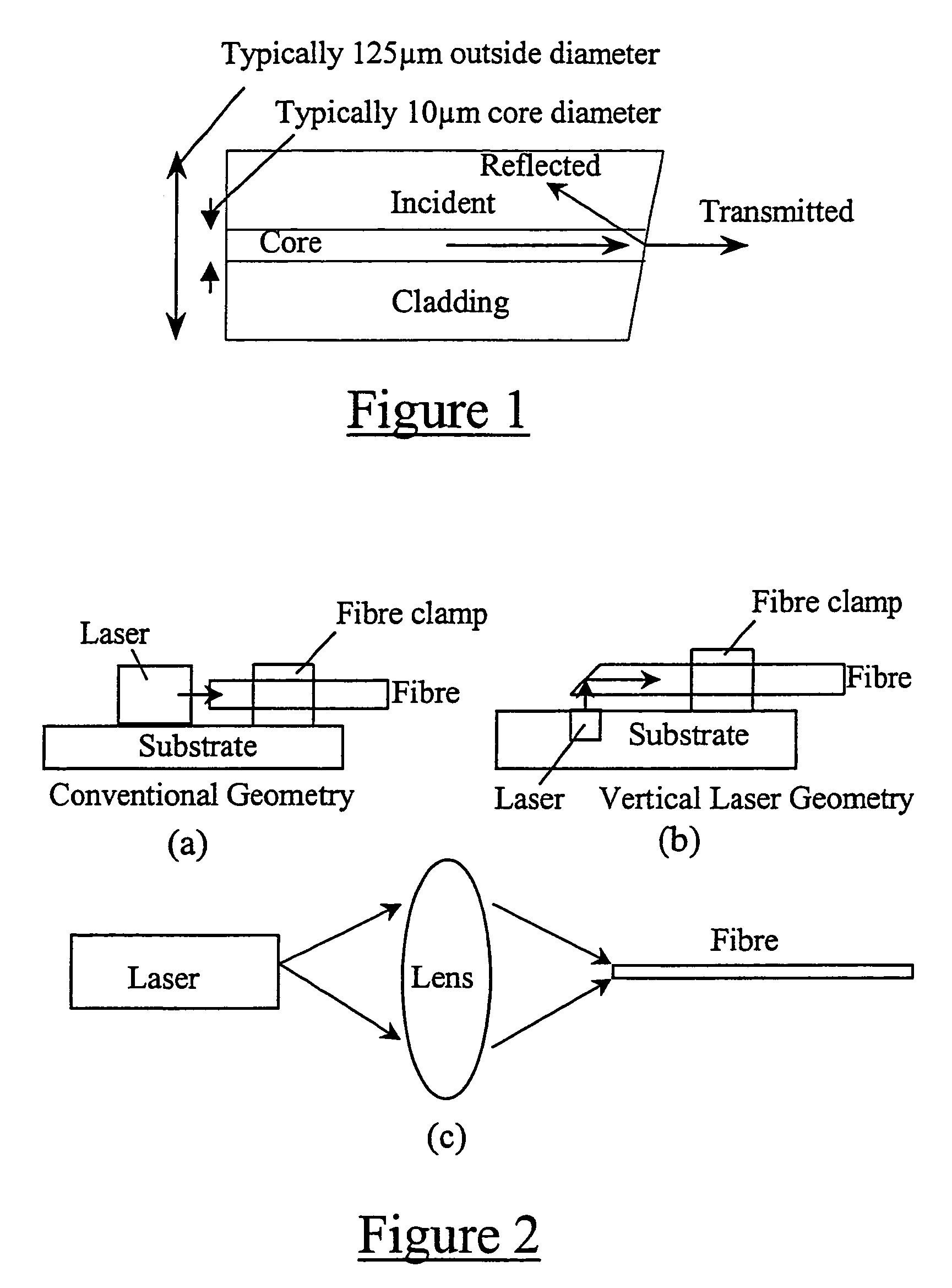
The problem here is to couple the divergent optical output from the laser diode, which will have an effective source size of a few microns and usually different beam divergences in the two orthogonal dimensions, into the (usually) circularly symmetric core of an optical fibre or waveguide which, for a single mode fibre or waveguide, will be between 3 and 20 μm in diameter, or may be up to 62 μm or more for multi-mode fibre or waveguides.
The production and alignment, assembly and subsequent permanent fixturing of these discrete components is problematic.
This results in a re-flow of material which is influenced by surface tension effects.
However, production of radii less than 10 μm is problematic with the micro-lathe technique.
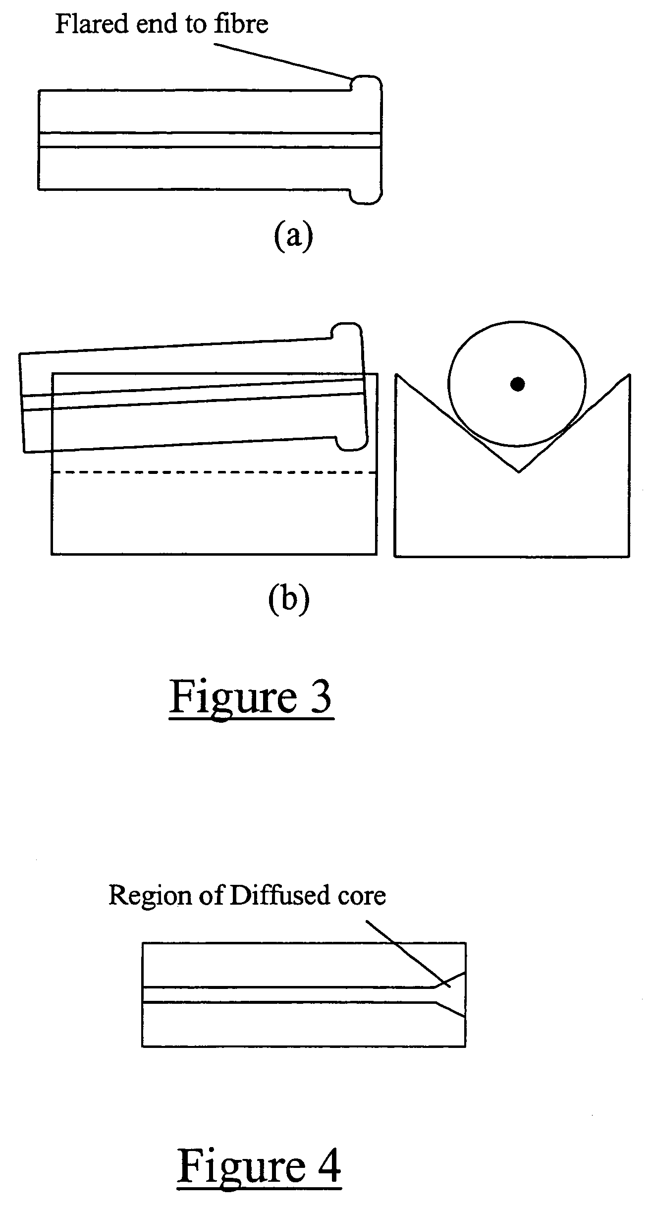
Moreover, in practice the technique is relatively slow (of order 15 s per fibre), and tends to “flare” the fibre, causing the fibre outside diameter (OD) to locally increase beyond the nominal 125 μm, as shown in FIG. 3(a).
This is a severe disadvantage if it is wished to passively align the fibre to an active device (say a laser source) by laying the fibre in a v-groove (FIG. 3(b)).
In such an application, the tolerance on alignment is typically of order 0.3 μm, and so even 1 μm levels of flare have a significant detrimental effect.
This core diffusion can have a deleterious effect on the optical performance of the lens.
Furthermore, the significant thermal input can cause severe problems when machining polarisation maintaining (PM) fibre, which typically have asymmetrically distributed inserts of a different or doped material within the fibre to provide stress directions and hence the PM axis.
If the laser lensing process produces a significant melt region, as the micro-lathe does, the effects of different parts of the end face of the fibre re-solidifying at different times can severely distort the overall surface form.

Method used


Image

  • Laser cutting method and apparatus for optical fibres or waveguides
  • Laser cutting method and apparatus for optical fibres or waveguides
  • Laser cutting method and apparatus for optical fibres or waveguides

Examples


Embodiment Construction

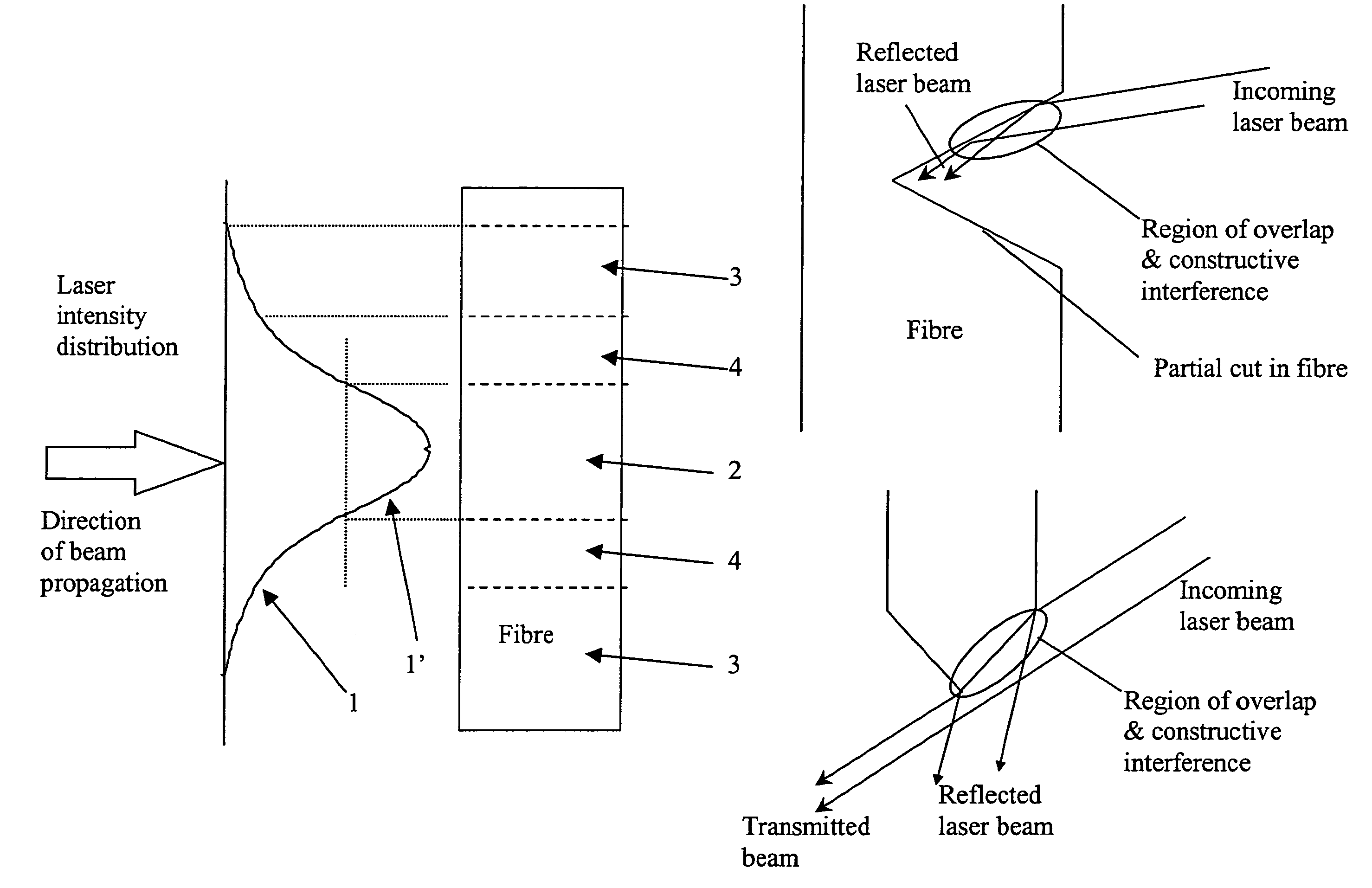
[0064]FIG. 5 illustrates, in schematic form, how the cutting action of a method of the invention is effected on a portion of optical fibre or waveguide so as to form an optical fibre or waveguide surface of enhanced quality. More specifically, as shown, the cutting action is affected by impinging an amount 1′ of a predetermined laser intensity distribution 1, for example in the form of a Gaussian intensity distribution 1, onto a section 2 (to be cut) of fibre or waveguide material 3 in alignment therewith and ablating or vaporising the fibre or waveguide section 2. Regions 4 of the fibre, adjacent to the fibre section 2, are further subjected to significant levels of heating in dependence upon the impingement, the regions 4 being heated to an appropriately significant level below the fibre or waveguide material's vaporisation point.

[0065]Advantageously, the laser cutting procedure of the invention does not involve the production of a mark on the fibre periphery and then mechanical f...


PUM

PropertyMeasurementUnit
wavelength rangeaaaaaaaaaa

Abstract

A cutting method and apparatus are provided to cut a portion of an optical fibre or waveguide with a laser beam. The proposed cutting action takes advantage of the sharp cutting edge of a laser beam generated so as to have a predetermined asymmetric intensity distribution. In operation, a prescribed amount of the beam distribution is impinged on the fibre or waveguide portion and causes the portion to ablate or vaporise so as to effect a cut at the portion in dependence upon the impingement. No translation of the laser beam across the fibre or waveguide is effected during cutting. The proposed cutting action bears definite advantages over conventional cutting techniques and finds utility for many optical fibre or waveguide applications. For example, the proposed cutting action can produce a substantially flat optical fibre or waveguide surface or a lens of enhanced quality at the end of the fibre or waveguide portion.

Description

FIELD OF THE INVENTION[0001]This invention relates to a laser cutting method and apparatus and more particularly, but not exclusively, concerns a cutting method and apparatus utilising a laser in optical fibre and optical waveguide applications.BACKGROUND OF THE INVENTION[0002]The state of the art to which the present invention relates is presented hereinafter in three parts, namely, in relation to: (1) the known technique of mechanical cleaving of optical fibres and optical waveguides, (2) the known techniques for producing lens-shapes on optical fibres, and (3) the known techniques for cutting optical fibres with a laser.1. Mechanical Cleaving of Optical Fibres and Waveguides[0003]The structure of a typical optical fibre is shown in FIG. 1 of the accompanying drawings. In a number of applications in fibre-optic communications it is necessary to couple light either into or out of optical fibres or waveguides. Sometimes this is accomplished using connectorised fibres where the fibre...

Claims


Application Information

Patent Timeline
Patent Type & Authority Patents(United States)
IPC IPC(8): G02B6/00G02B6/26B23K26/073B23K26/38B23K26/40G02B6/25G02B6/42
CPCB23K26/0734G02B6/25G02B6/4203G02B6/4214
Inventor OSBORNE, MICHAEL
Owner IRUVIS LTD
Learn More