
Portable fuel storage tank leak detection system

a leak detection and storage tank technology, applied in the direction of fluid tightness measurement, instruments, machines/engines, etc., can solve the problems of tank leakage, lack of cost-effective solution for mandatory leak detection testing, and inability to meet performance standards, etc., to achieve short test duration, improve accuracy, and reduce costs

Inactive Publication Date: 2006-12-05
NAVY SEC OF THE AS REPRSENTED BY THE UNITED STATES BY THE UNITES OF AMERICA
View PDF5 Cites 9 Cited by
  • Summary
  • Abstract
  • Description
  • Claims
  • Application Information

AI Technical Summary

Benefits of technology

[0011]The leak detection system comprising the present invention is a major improvement over current apparatus and method for leak detection by providing superior accuracy, flexibility, portability, and short test duration all at significantly lower costs over prior methods and apparatus. The leak detection system operates as a low range differential pressure (LRDP) system and achieves a very high level of performance detecting small leaks because of it is very precise and also compensates for thermal expansion and contraction of the fuel in the tank, the instrumentation, and the tank utilizing a commercially available differential pressure sensor. The leak detection system also provides for a portable and highly cost-effective method for complying with both monthly and annual regulatory tank testing standards and can service multiple tanks in a fuel tank farm.

Problems solved by technology

Existing technologies either cannot meet performance standards for the large 50,000 to 100,000 gallon USTs or do not provide for a cost-effective solution to mandatory leak detection testing.
If the tracer chemical is found in the monitoring well samples, the tank is declared to be leaking.
There are however technical problems associated with this method of leak detection.
Also, the cost of the tracer method is very expensive due to recurring sampling and analysis costs.
However these systems, which are certified for 10,000 gallon tanks, do not meet performance standards for the 50,000 to 100,000 gallon tanks.
However, bulk leak detection systems are very expensive, heavy, usually non-portable, can be very slow to stabilize, and may require rigorous operator input and analysis.
However, this method is very labor intensive in that is requires daily hands-on monitoring.
This method does not work well for tanks having a low frequency of fuel transfers (typical of larger tanks), and cannot detect leaks in real time.

Method used


Image

  • Portable fuel storage tank leak detection system
  • Portable fuel storage tank leak detection system
  • Portable fuel storage tank leak detection system

Examples


Embodiment Construction

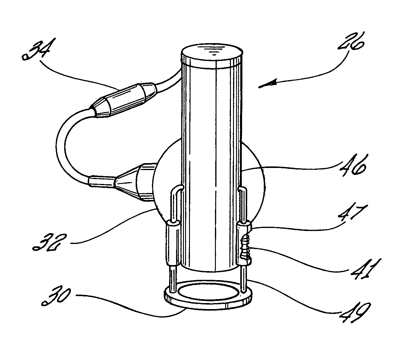
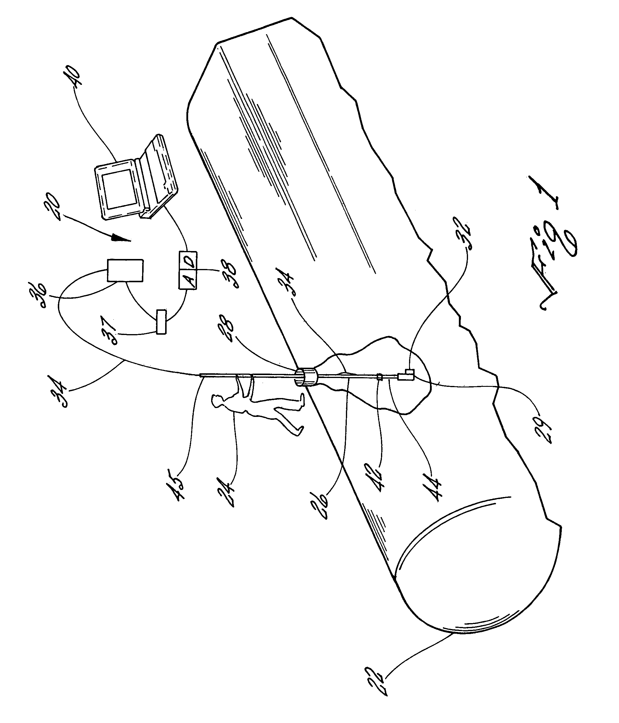
[0027]Referring to FIG. 1, the leak detection system 20, designed to test for fuel in underground fuel storage tanks, is first inserted into an underground fuel storage tank 22 which contains jet fuel. The operator 24 lowers a reference tube 26 into the storage tank 22 through an 8-inch diameter tank access port 28. The reference tube 26 rest on the bottom of the storage tank 22 when the reference tube 26 is fully inserted into the tank 22. The reference tube 26, which is a shaped reference tube having diameter of ¼″ to 6″, is equal to or greater in length than the diameter of tank 22.

[0028]Leak detection system 20 includes a sliding seal 29 which is affixed to the bottom end of the reference tube 26. A differential pressure transducer 32 mounted on the side of the reference tube 26 adjacent to the sliding seal 29. Differential pressure transducer 32 and reference tube 26 each have planar faces which are clamped and sealed directly against each other.

[0029]Electrical conductors / cabl...


PUM


Abstract

A portable fuel storage tank leak detection system for detecting fuel leaks from a fuel storage tank at a leak rate of 0.1 gallons per hour. The leak detection system provides for a probability of detection of at least 95% and a probability of false alarm of no more than 5%.

Description

BACKGROUND OF THE INVENTION[0001]1. Field of the Invention[0002]The present invention relates generally to a system for leak detection in storage tanks. More specifically, the present invention relates to a portable rapid test leak detection system for accurate and reliable leak detection in underground storage tanks which have a fuel storage capacity of between 50,000 gallons and 100,000 gallons.[0003]2. Description of the Prior Art[0004]In 1988, Environmental Protection Agency issued to the States Underground Storage Tank (UST) regulations for fuel storage. The UST regulations were issued to implement monthly monitoring and annual tightness testing of the USTs. Monthly monitoring of USTs requires that a leak detection system be certified to detect a leak rate of 0.2 gallons per hour (GPH) and annual tightness testing requires a certification to detect a leak rate of 0.1 GPH. Each certification requires a probability of detection of at least 95% and a probability of false alarm of ...

Claims


Application Information

Patent Timeline
Patent Type & Authority Patents(United States)
IPC IPC(8): G01M3/04
CPCG01M3/3263
Inventor MAJOR, WILLIAM R.KARR, LESLIE A.
Owner NAVY SEC OF THE AS REPRSENTED BY THE UNITED STATES BY THE UNITES OF AMERICA
Learn More