Wood gasification apparatus

a gasification apparatus and wood technology, applied in the field of wood gasification apparatus, can solve the problems of hindering the flow of particulate materials into the housing, and achieve the effect of high flow rate of water vapor and hindering the flow of particulate materials

Inactive Publication Date: 2006-12-05
BIO GAS TECH
View PDF15 Cites 32 Cited by
  • Summary
  • Abstract
  • Description
  • Claims
  • Application Information

AI Technical Summary

Benefits of technology

[0006]The invention is embodied in an apparatus that includes a housing having an inlet and an outlet. A rotatable auger is mounted in the housing, and includes surfaces defining at least one spiral channel. The spiral channel is tapered from a first depth adjacent the housing inlet and to a second, lesser depth adjacent the housing outlet. The auger is rotatable to propel particulate materials from the housing inlet toward the housing outlet. As the particulate materials are moved along the auger they are frictionally heated to a first temperature sufficient to remove moisture from the particulate material. The auger and the housing define a second region wherein the particulate material is frictionally heated to a second temperature sufficient to convert at least a portion of the particulate material to a gas. In one embodiment, as the particulate material is frictionally heated and propelled along the auger, it reaches a plasticizing temperature, and forms a seal between the auger and the housing. The seal prevents gas from flowing back along the auger to the housing inlet, and reduces the possibility that combustible gas could escape from the housing inlet.

Problems solved by technology

The high flow rate of water vapor out through the inlet can in some instances hinder the flow of particulate material into the housing.

Method used


Image

  • Wood gasification apparatus
  • Wood gasification apparatus
  • Wood gasification apparatus

Examples


Embodiment Construction

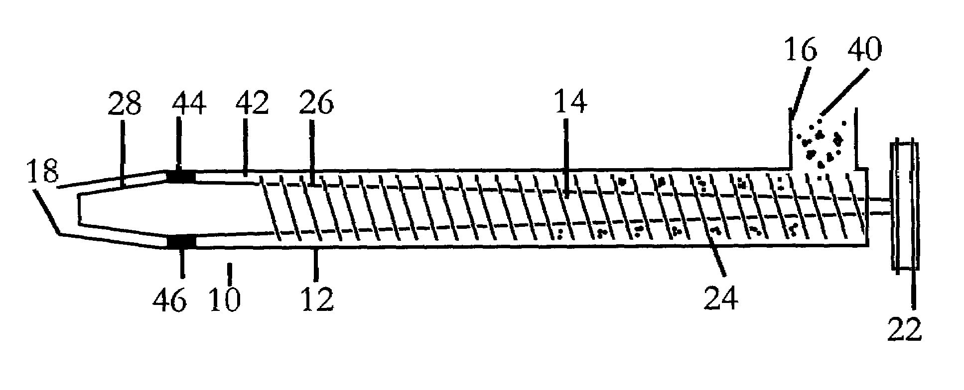
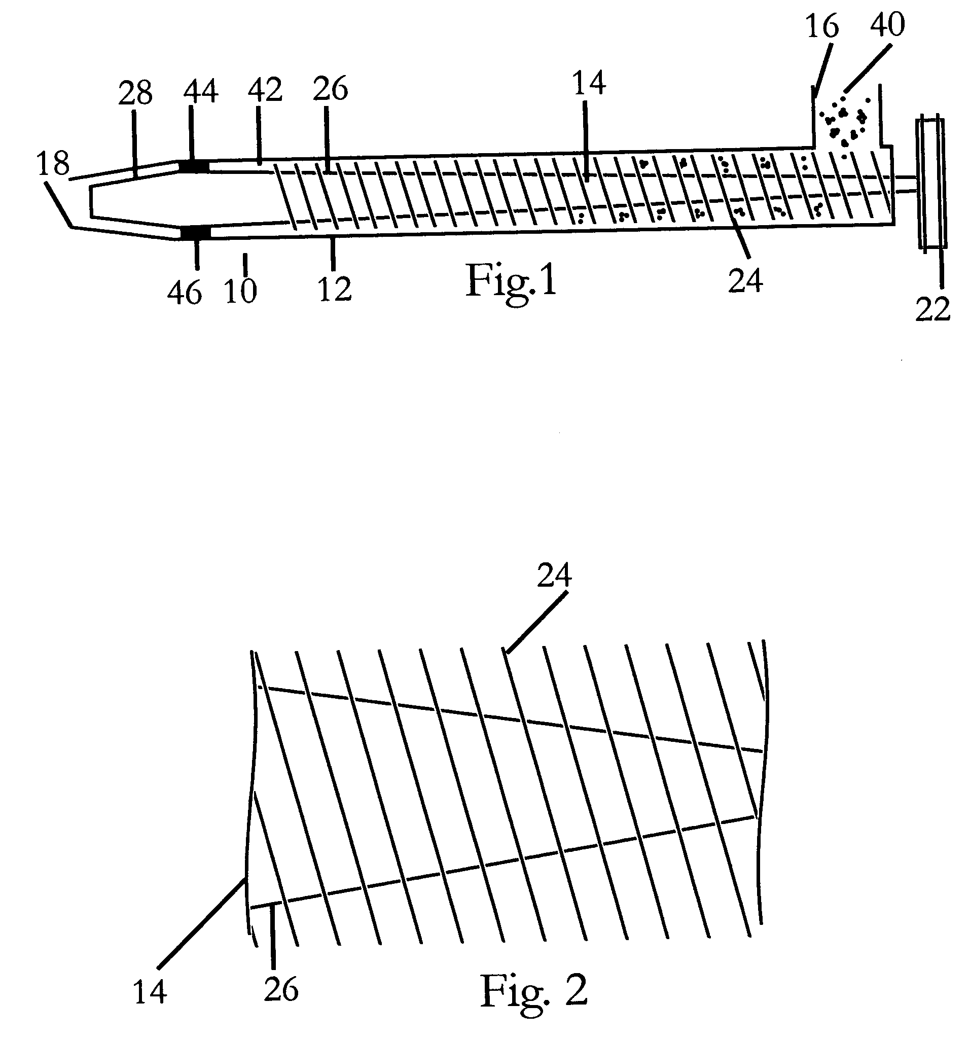
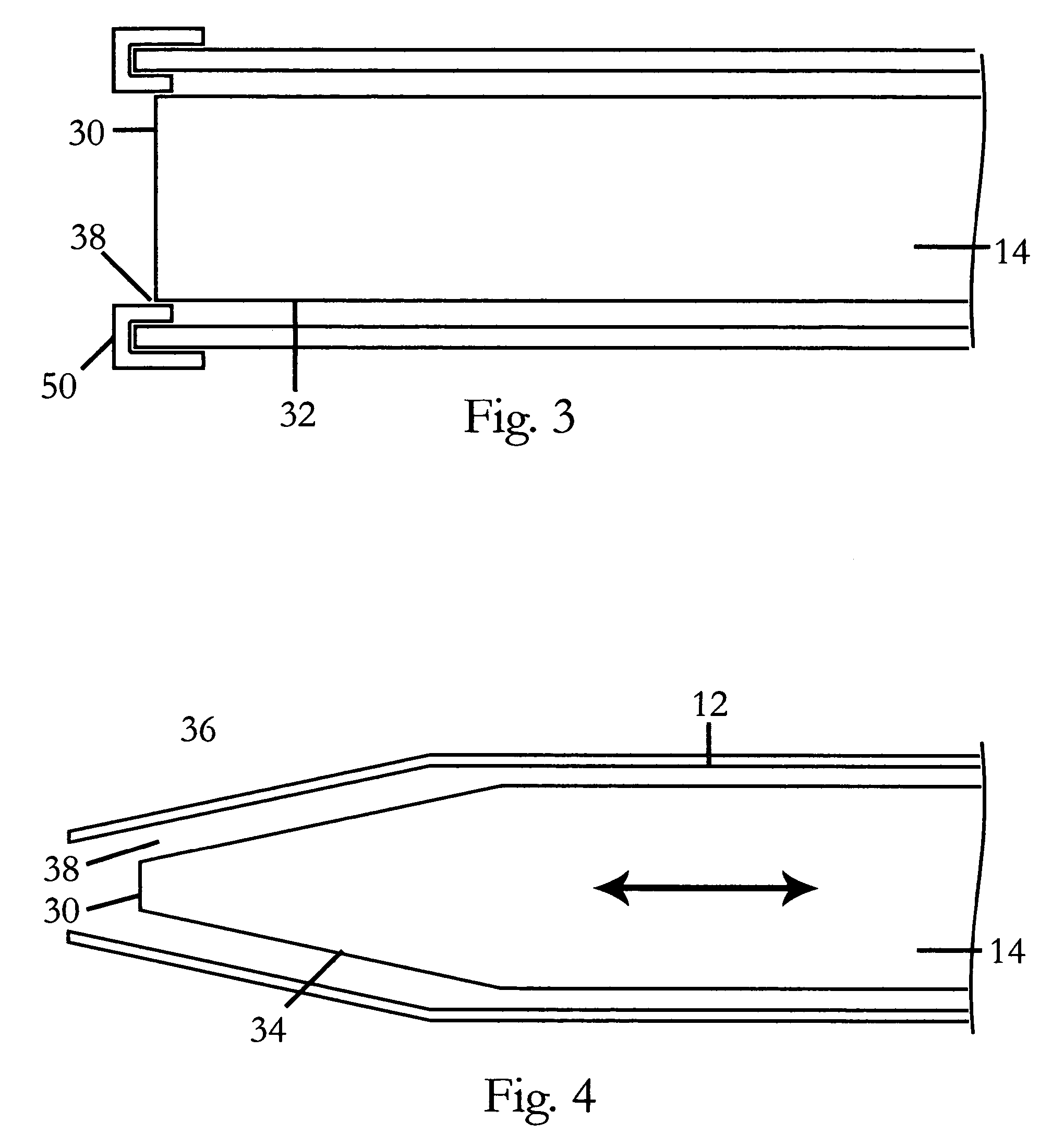
[0016]Turning now to FIG. 1, the a preferred embodiment of the invention is shown generally at 10, and includes a housing 12 and an auger 14. Housing 12 includes an inlet 16 and an outlet 18 spaced apart along bore 20. Auger 14 is driven by motor (not shown) and a belt and sheave assembly 22. Auger 14 includes a continual spiral blade 24 that propels materials through housing 12 as auger 14 is rotated. The spiral blade 24 defines a continually tapering spiral channel 26 which completely tapers to a flat surface 28. Auger 14 includes end portion 30 that includes a flat surface 32, and in one embodiment a tapered portion 34. Tapered auger portion 34 is sized and shaped to fit closely in tapered portion 36 of housing 12, defining an annular discharge opening 38. The clearance between tapered auger portion 34 and tapered housing portion 36 is ideally maintained at about 0.010″. In one preferred embodiment (FIG. 4) the clearance can be varied by adjusting the axial position of auger 14 i...


PUM

PropertyMeasurementUnit
depthaaaaaaaaaa
temperatureaaaaaaaaaa
cross-sectional areaaaaaaaaaaa

Abstract

A wood gasification apparatus in which cellulosic material is transported by an auger through a housing and heated to vaporize at least a portion of the cellulosic material by frictional heating. The auger and housing define a spiral void through which the cellulosic material is propelled from the inlet to the outlet, and which continually decreases in volume from the inlet to the outlet. The ever decreasing volume of the void increases the pressure on the cellulosic material and maximizes the frictional heating until the material reaches a vaporization temperature.

Description

BACKGROUND OF THE INVENTION[0001]This invention relates to wood gasification, and in particular to a continuous wood gasification apparatus.FIELD OF THE INVENTION[0002]The gasification of wood can be generally described as the heating of wood to converts the cellulosic material into a combination of combustible fuel gases that typically contains methane, hydrogen, and carbon monoxide. A commercially viable process for the gasification of wood has so far eluded those working in the field. Were such a process to be achieved, numerous applications would be immediately available. One application would be the use of wood waste by sawmills and other wood processing facilities to generate heat and electricity for plant operations.[0003]Most efforts at wood gasification center around large, countercurrent heat exchangers that combust a portion of the wood waste to generate a hot combustion gas stream. The hot combustion gas stream is then contacted with a packed bed of wood chips at a suffi...

Claims


Application Information

Patent Timeline
Patent Type & Authority Patents(United States)
IPC IPC(8): B01J19/00
CPCC10B7/10C10B53/02C10B57/02C10J3/32C10J2300/0909C10J2300/092Y02E50/14Y02E50/10
Inventor SMITH, DAVID NIXONFERRELL, ALLEN RICE
Owner BIO GAS TECH
Why Eureka
Try Eureka