
Memory cell and method for fabricating it

Inactive Publication Date: 2006-12-05
POLARIS INNOVATIONS
View PDF5 Cites 0 Cited by
  • Summary
  • Abstract
  • Description
  • Claims
  • Application Information

AI Technical Summary

Benefits of technology

[0019]Consequently, it is an essential advantage of the present invention that it is possible to provide memory cell structures with an increased storage capacitance without an upper region of a trench-type structure growing over due to formation of grain elements. Furthermore, the resulting structure is advantageous for integration since an Al2O3 layer provided in an upper region of the trench structure is stressed uniformly during removal of a silicon in an upper region, but during an etching-back of grain elements that arise in the upper region according to the prior art, the regions that are not covered by grain elements are etched to a greater extent.
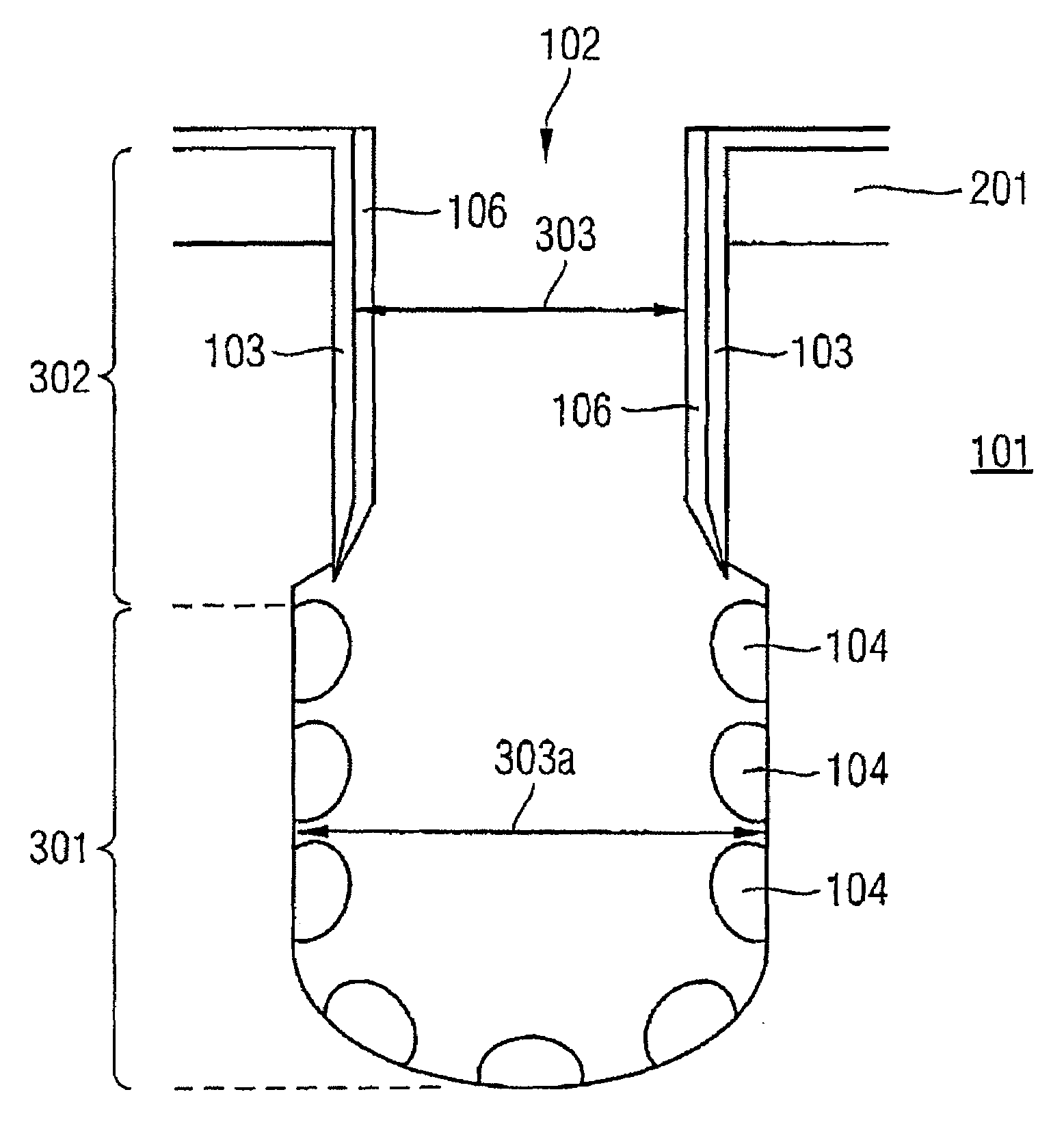
[0020]Consequently, the heart of the invention consists in depositing an amorphous silicon layer on the inner areas of the trench-type depression in such a way that the amorphous silicon layer is closed in the collar region, while the amorphous silicon layer does not form a closed structure in an electrode region forming the lower region of the trench-type depression, and in growing grain elements selectively on the inner areas of the trench-type depression in the electrode region, the amorphous silicon layer continuing to grow in the collar region of the trench-type depression.
[0021]In an advantageous manner, such a two-stage deposition can be realized in a single furnace process.
[0022]The method according to the invention for fabricating a memory cell essentially has the following steps:
[0025]c) non-conformally depositing a barrier layer in the trench-type depression of the substrate in such a way that the barrier layer covers an inner area of the trench-type depression only in a collar region forming an upper region of the trench-type depression;
[0026]d) growing grain elements on the inner areas of the trench-type depression, the surfaces of the grain elements together with the inner areas of the trench-type depression forming areas of a first electrode of the memory cell and deposited material being removed in the collar region;

Problems solved by technology

However, producing no longer only planar areas but also areas that are at an angle with respect to a reference area (the angle ranges through to 90° and beyond) gives rise to problems which can prevent patterning of such angled areas with lithography.
A principal disadvantage of methods according to the prior art is that the fabrication of a memory cell is made considerably more difficult by grains K2 growing together in such a way in the upper region of the trench-type depression.

Method used


Image

  • Memory cell and method for fabricating it
  • Memory cell and method for fabricating it
  • Memory cell and method for fabricating it

Examples


Embodiment Construction

[0059]In the figures, identical reference symbols designate identical or functionally identical components or steps.

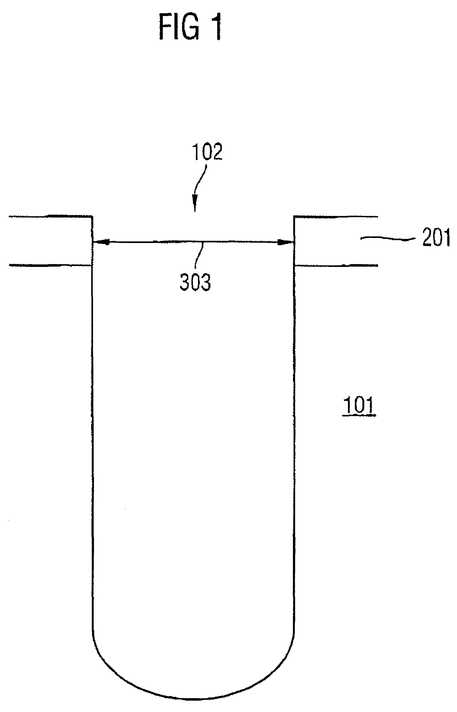
[0060]FIG. 1 shows a silicon substrate 101, to which a nitride layer is applied as a protective layer (a pad nitride). Furthermore, a trench-type depression (deep trench) 102 having a width 303 of typically 20 nm to 500 nm is etched into the substrate 101 shown in FIG. 1. The arrangement shown in FIG. 1 forms a basic element for fabricating a memory cell according to the invention.

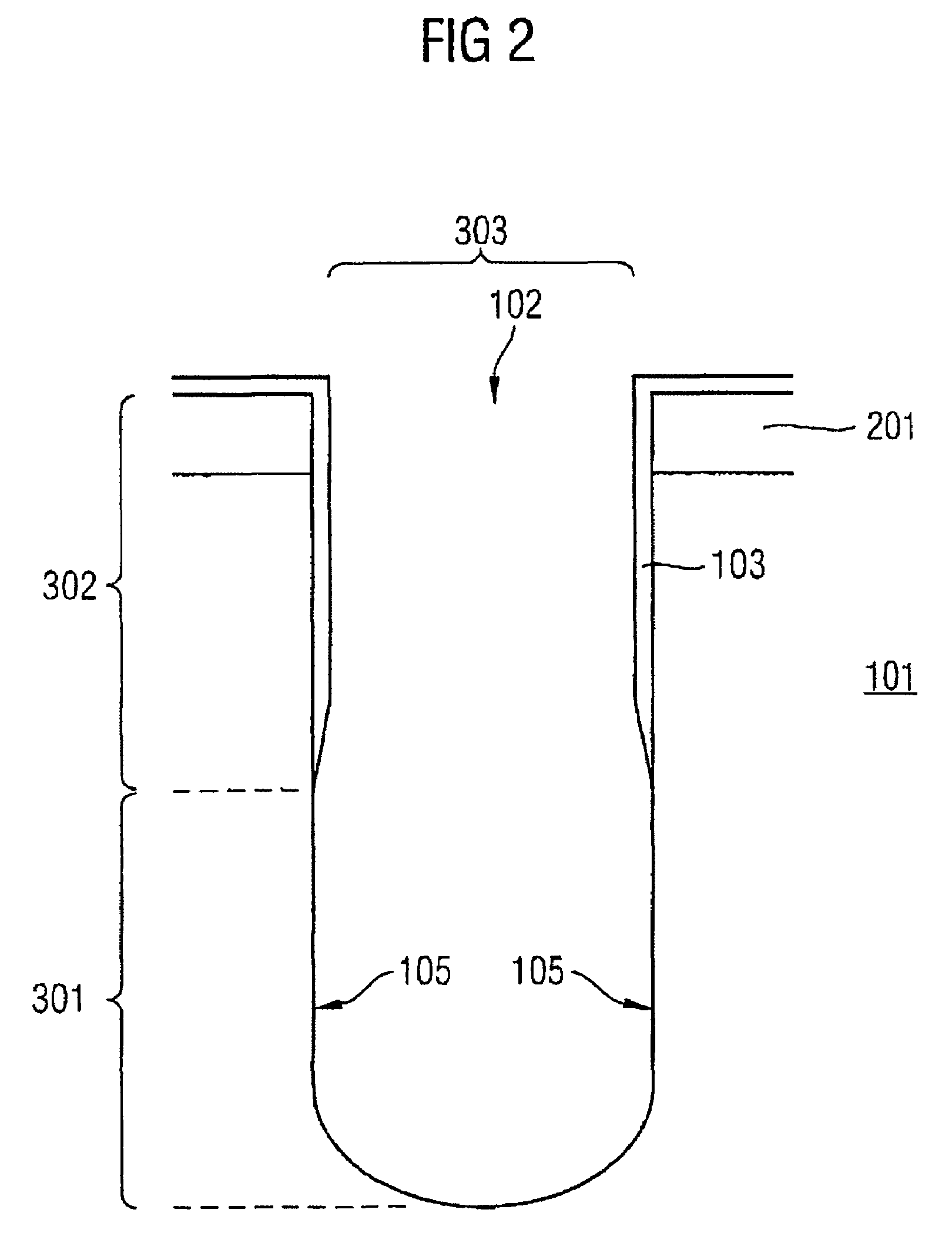
[0061]FIG. 2 shows the arrangement illustrated in FIG. 1 after deposition of a barrier layer 103 in a collar region 302 forming an upper region of the trench-type depression 102.

[0062]It should be pointed out that in FIG. 2 and the subsequent figures, those elements that have already been described in previous figures are not described anew in order to shorten the illustration.

[0063]In an electrode region 301 forming a lower region of the trench-type structure 102, inner areas 105 have remain...


PUM


Abstract

The invention provides a method for fabricating a memory cell, a substrate (101) being provided, a trench-type depression (102) being etched into the substrate (101), a barrier layer (103) being deposited non-conformally in the trench-type depression (102), grain elements (104) being grown on the inner areas of the trench-type depression (102), a dielectric layer (202) being deposited on the surfaces of the grain elements and the inner areas of the trench-type depression, and a conduction layer being deposited on the dielectric layer, the grain elements (104) growing selectively on the inner areas (105) of the trench-type depression (102) in an electrode region (301) forming a lower region of the trench-type depression (102) and an amorphous silicon layer continuing to grow in a collar region (302) forming an upper region of the trench-type depression (102).

Description

TECHNICAL FIELD[0001]The present invention relates generally to a method for influencing grain sizes of grain elements which grow on different layer materials, in particular a method for influencing grain sizes of grain elements which are used in memory cells for increasing a capacitance of the memory cells, and relates specifically to a method for fabricating a memory cell, in which a substrate is provided, a trench-type depression is etched into the substrate, a barrier layer is deposited in the trench-type depression of the substrate in a non-conformal manner in such a way that the barrier layer covers an inner area of the trench-type depression only in a collar region forming an upper region of the trench-type depression, grain elements are grown on the inner areas of the trench-type depression, the surfaces of the grain elements together with the inner areas of the trench-type depression forming areas of a first electrode of the memory cell, a dielectric layer is deposited on t...

Claims


Application Information

Patent Timeline
IPC IPC(8): H01L21/8242H01L21/8239H01L21/334H01L21/8229H01L29/94
CPCH01L29/66181H01L29/945H10B99/00
Inventor BIRNER, ALBERTFOERSTER, MATTHIASHECHT, THOMASSTADTMUELLER, MICHAELORTH, ANDREAS
Owner POLARIS INNOVATIONS
Learn More