Scanning optical printhead having exposure correction

a technology of optical printhead and exposure correction, which is applied in the direction of printing, discharge tube/lamp details, instruments, etc., can solve the problems of linear array printers, high cost apparatuses, and different set of difficulties in controlling exposure time t, so as to increase printer throughput and low cost

Inactive Publication Date: 2006-12-05
CARESTREAM HEALTH INC
View PDF23 Cites 30 Cited by
  • Summary
  • Abstract
  • Description
  • Claims
  • Application Information

AI Technical Summary

Benefits of technology

[0020]It is an advantage of the present invention that it provides a scanned optical printhead having a high duty cycle, able to provide exposure energy during acceleration and deceleration, thus increasing printer throughput.
[0021]It is an advantage of the present invention that it provides an imaging solution for photosensitive media that can be scaled to suit a range of media widths, in contrast to laser scanning apparatus or drum-based imaging apparatus.
[0022]It is an advantage of the present invention that it allows the design of a compact printing apparatus for high-resolution optical imaging.
[0023]It is a further advantage of the present invention that it allows the use of a low-cost LED array as a linear exposure source.
[0024]It is a further advantage of the present invention that it enables low cost components to be used for carriage movement across the surface of the photosensitive medium.

Problems solved by technology

However, where only a portion of the image is exposed at a time, such as with the polygon scanner or linear light modulator approach, control of exposure time t becomes more complex.
Both of these references, however, are high cost apparatuses.
Linear array printers present a different set of difficulties.
), it is considered to be impractical and expensive to implement a scanning mechanism that, by itself, provides the required precision needed for transporting a photosensitive media past a linear array of exposure sources without some amount of error, which results in banding or other motion-related non-uniformities in the output image.
Both U.S. Pat. Nos. 6,037,584 and 6,576,883 provide useful techniques for input optical scanning using a linear sensor, however, the challenges faced in printing by exposure from an array of light sources are considerably more formidable, due to higher resolution and positional accuracy requirements and to response sensitivity characteristics of the photosensitive medium itself.
This arrangement is suitable for the large-format prepress imaging environment; however the size, complexity, and expense of a rotating vacuum drum prevents the use of this type of solution in a low-cost desktop optical printing system.
Again, however, while corrective measures applied to the apparatus design compensate for tolerance errors in both position and timing, the end-result is suitable only for optical sensing or for ink jet droplet placement.
The challenge of high-resolution optical printing using a carriage-mounted printhead, are not addressed in either U.S. Pat. Nos. 6,037,584; 6,576,883; or U.S. Pat. No. 6,422,682 and not satisfactorily met using solutions that have worked for prepress imaging systems.
Again, however, while conventional use of an encoder strip provides sufficient accuracy for ink droplet placement at the needed resolution, optical imaging requires significantly finer resolution.
Moreover, the number of individual channels in a linear optical printhead must be kept low due to power dissipation in the printhead.
This conventional approach, however, does not allow optical printhead design to benefit from some of the advantages of carriage mounting designs, including compact size (particularly when using LED arrays), reduced cost for lower manufacturing volumes, and improved throughput.

Method used


Image

  • Scanning optical printhead having exposure correction
  • Scanning optical printhead having exposure correction
  • Scanning optical printhead having exposure correction

Examples


Embodiment Construction

[0033]The present description is directed in particular to elements forming part of, or cooperating more directly with, apparatus in accordance with the invention. It is to be understood that elements not specifically shown or described may take various forms well known to those skilled in the art.

Hardware Components

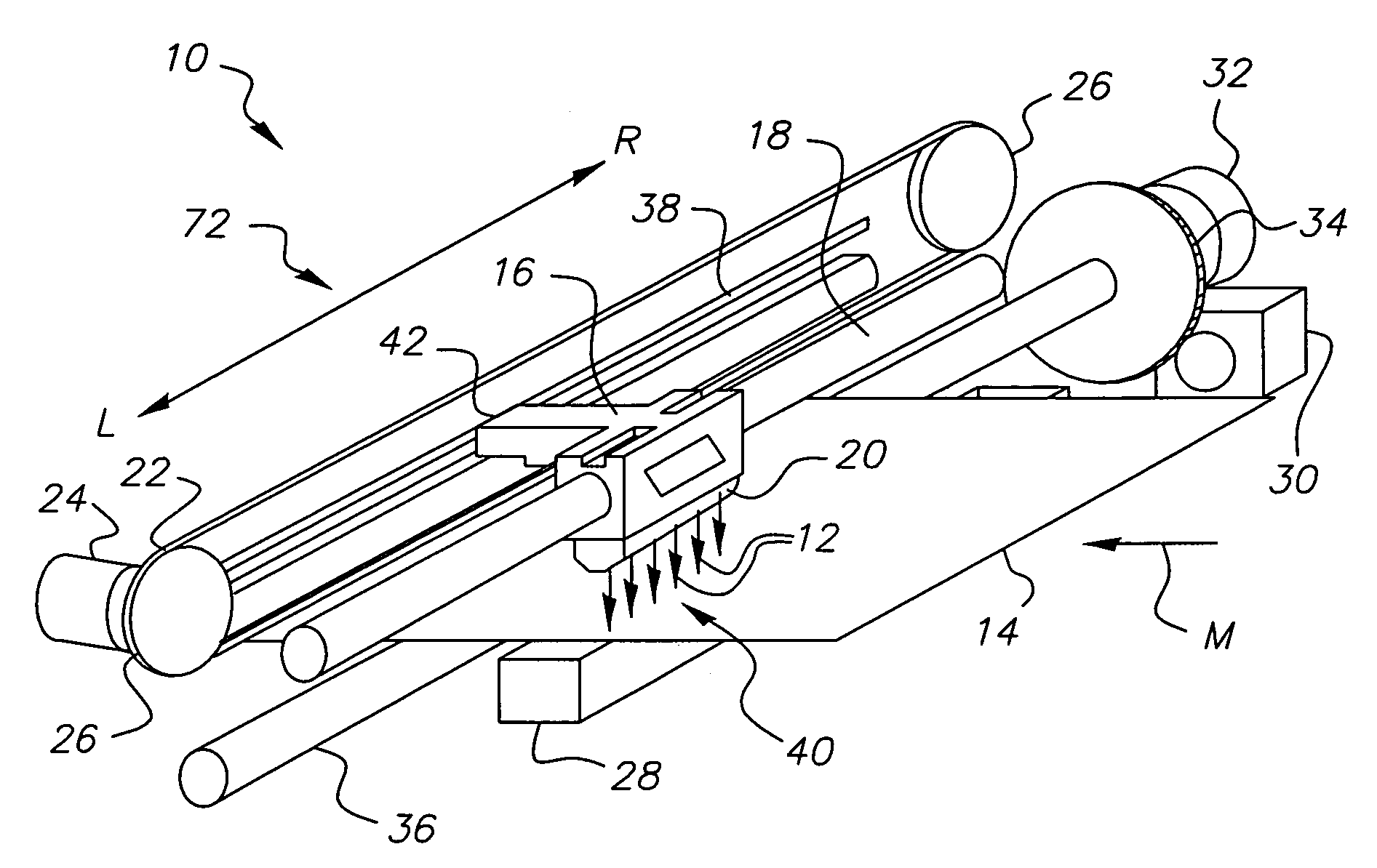
[0034]Referring to FIG. 1, there is shown a perspective view of essential hardware components of a printing apparatus 10 of one embodiment of the present invention. A printhead 20 having a plurality of exposure sources 12 arranged as a linear array of exposure sources 40 is reciprocated within a carriage assembly 72 between a left position L and a right position R in order to expose pixels onto a photosensitive medium 14 in a series of swaths. Printhead 20 is mounted in a carriage-mount arrangement, in which a shuttle 16 is propelled along a rail support 18 by a belt drive 22. A drive motor 24 and pulleys 26 are arranged to move shuttle 16 back and forth in reciprocating...


PUM


Abstract

A printing apparatus 10 exposes an image onto a photosensitive medium 14, having a printhead 20 with a linear array of exposure sources 40, each exposure source 12 operable at a variable intensity. A shuttle mechanism 16 moves the printhead 20 over the photosensitive medium 14 in a reciprocating motion between one end of a carriage assembly 72 and the other. An encoder 38 is coupled to the shuttle mechanism (16) for providing an index encoder pulse 60 at each of a plurality of increments of position of the shuttle mechanism 16 along the carriage assembly 72. Exposure control logic calculates a shuttle velocity according to index signal timing and adjusts the variable intensity of each exposure source 12 according to the shuttle velocity.

Description

CROSS REFERENCE TO RELATED APPLICATIONS[0001]Reference is made to the following commonly-assigned copending U.S. patent application Ser. No. 10 / 700,832, filed Nov. 4, 2003, entitled MULTICHANNEL PRINTHEAD FOR PHOTOSENSITIVE MEDIA, by Narayan et al., the disclosure of which is incorporated herein.FIELD OF THE INVENTION[0002]This invention generally relates to printing apparatus for photosensitive media and more particularly relates to a scanning optical printhead using a carriage-mounted linear exposure array with exposure control.BACKGROUND OF THE INVENTION[0003]When high-quality images are needed, such as for diagnostic imaging applications, photosensitive media, such as film, paper, and other photosensitized substrates have marked advantages over many other types of substrates. In order to tap these advantages for images that are obtained or stored as digital data, a number of electronic printers have been developed.[0004]One approach for exposure of a digital image onto a photose...

Claims


Application Information

Patent Timeline
Patent Type & Authority Patents(United States)
IPC IPC(8): B41J2/435B41J29/38B41J29/393
CPCB41J29/393
Inventor HAWVER, JEFFERY R.
Owner CARESTREAM HEALTH INC
Why Eureka
Try Eureka