

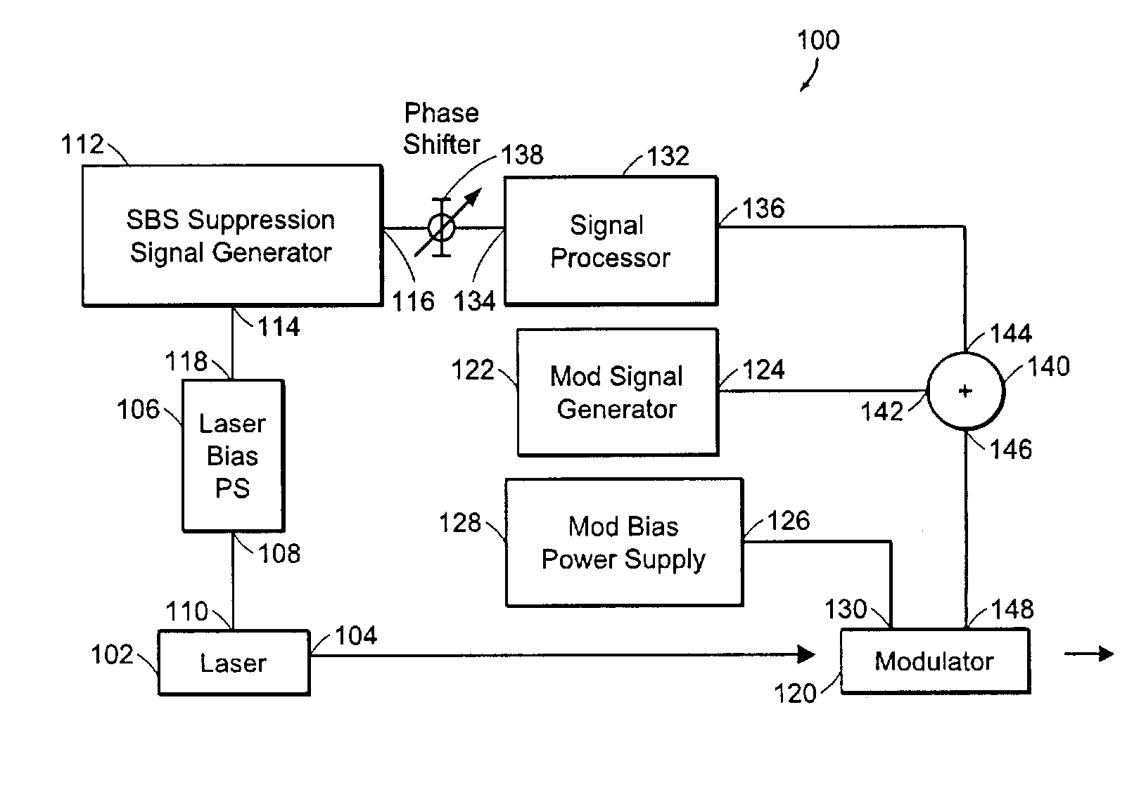
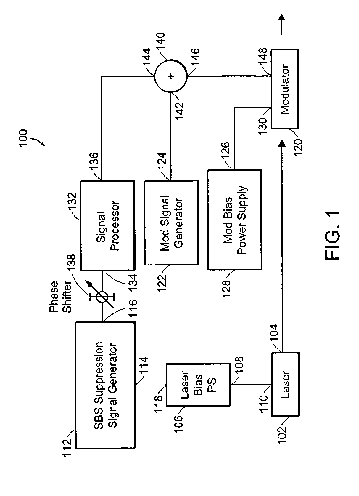
Optical transmitter with SBS suppression
- Summary
- Abstract
- Description
- Claims
- Application Information
AI Technical Summary
Benefits of technology
Problems solved by technology
Method used
Image

Examples
Embodiment Construction
[0016]Optical fibers used for communications exhibit stimulated Brillouin scattering (SBS) at optical signal power levels that are as low as ˜1 mW in some optical fibers. The threshold optical power that causes SBS can be expressed by the following equation:
/ th≅21(α / GB)
[0017]where the parameter α represents absorption in the optical fiber and the parameter GB represents the peak gain, which is approximately 5×10⁻¹¹ m / W for narrow-bandwidth signals used for communications. The peak gain decreases as the incident optical signal bandwidth increases. For example, an optical fiber having an effective area of 50 μm2, and having an absorption coefficient α≅0.2 dB / km, will exhibit a threshold optical power level which causes SBS that is approximately 2.4 mW for an optical fiber length that is approximately 20 km.
[0018]Optical power levels that exceed the threshold optical power will cause the SBS to rapidly rise until the SBS limits the power that can be transmitted through the optical fibe...
PUM
| Property | Measurement | Unit |
|---|---|---|
| Current | aaaaa | aaaaa |
| Width | aaaaa | aaaaa |
| Phase | aaaaa | aaaaa |
Abstract
Description
Claims
Application Information