Direct conversion receiver with DC offset compensation and method thereof

a direct conversion and compensation technology, applied in the field of direct conversion receivers, can solve the problems of inaccurate data decoding, bias dc offset, and indirect conversion receivers also have drawbacks, and achieve the effect of fast and accurate dc offset compensation and slow but accurate compensation

Active Publication Date: 2006-12-05
VIA TECH INC
View PDF6 Cites 11 Cited by
  • Summary
  • Abstract
  • Description
  • Claims
  • Application Information

AI Technical Summary

Benefits of technology

[0014]The object of the present invention is to provide an apparatus and method for DC offset compensation in a direct conversion receiver of a mobile phone, which performs a fast and accurate DC offset compensation.
[0017]Thus, by first using a digital controller to obtain the DC offset value to perform a fast coarse compensation and then using a track-and-hold circuit to perform a relatively slow but accurate compensation, the direct conversion receiver of the invention accomplishes a fast and accurate DC offset compensation.

Problems solved by technology

However, direct conversion receivers also have drawbacks.
As a result, a signal that is received from a transmitter can be further distorted, and thereby lead to inaccurate data decoding.
However, the estimate introduces a bias DC offset, due to the finite amount of data used for estimating the DC-offset.
Furthermore, since the transmitted data is unknown, it is impossible to compensate for for the bias DC offset in the signal before it is supplied to the decoder unless a large amount of data is received (in which the bias DC offset will be reduced to zero) or both the transmitted symbols and the channel are known.
However, while this solves the bias DC offset problem, the dynamics in the decoder will be too large because the DC-offset level can be several decibels (dB) larger than the received signal.
Also, numerical problems are encountered when estimating the radio channel and the DC-offset simultaneously because of the magnitude difference between the channel parameters and the DC component.
However, the receiver of the U.S. Pat. No. 6,298,226 needs a relatively long time to complete the DC offset compensation due to the charging time period of the capacitor in the track-and-hold circuit.

Method used


Image

  • Direct conversion receiver with DC offset compensation and method thereof
  • Direct conversion receiver with DC offset compensation and method thereof
  • Direct conversion receiver with DC offset compensation and method thereof

Examples


Embodiment Construction

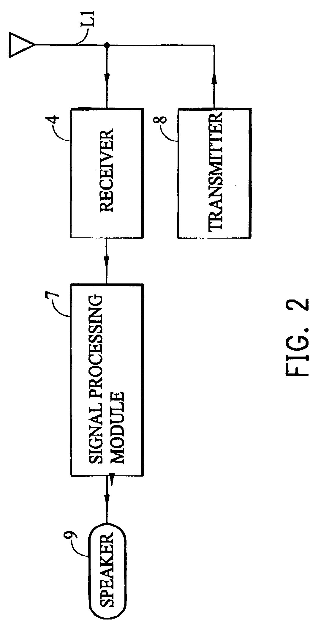
[0027]FIG. 2 shows an schematic illustration of the receive path of a mobile phone. The receive path comprises an antenna 61, an RF receiver 4 (hereinafter referred to as receiver), a signal processing module 7 and a speaker 9. The receiver 4 is interconnected between the antenna 61 and the signal processing module 7 connected to the speaker 9. The mobile phone further includes a transmit path indicated in FIG. 2 by means of a transmitter 8 connected to the antenna 61. The RF receiver 4 typically includes several groups of amplifiers separated by frequency-changing circuits (e.g., mixers) to extract information carried by a weak signal voltage that appears at terminals of the antenna 61. The receiver 4 outputs a baseband signal input to the signal processing module 7 for further processing.

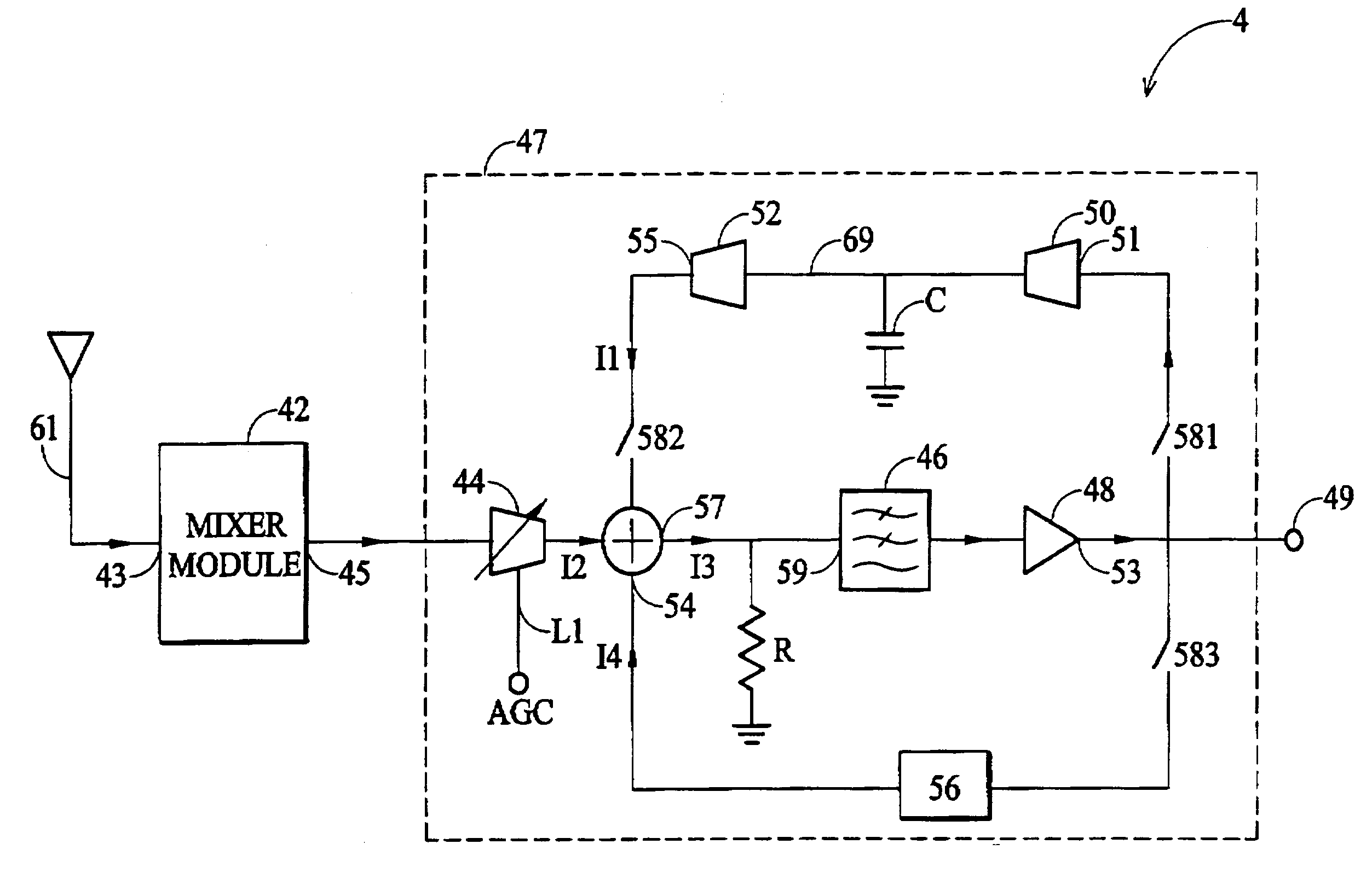
[0028]FIG. 3 is a diagram showing a direct conversion receiver according to one embodiment of the invention. The receiver 4 includes a mixer module 42 and an amplifier module 47. The mixer module ...


PUM


Abstract

A direct conversion receiver with DC offset compensation. The receiver includes an antenna receiving a RF signal, a mixture module converting the RF signal to a baseband signal, a gain amplifier amplifying the baseband signal, an adder subtracting a DC offset current from the baseband signal, a DC offset cancellation circuit obtaining and converting a DC offset value to the DC offset current, a track-and-hold circuit receiving the baseband signal, holding and transferring a DC offset voltage to the DC offset current, and a switching circuit alternatively coupling and decoupling the DC offset cancellation and track-and-hold circuit to receive the baseband signal.

Description

BACKGROUND OF THE INVENTION[0001]1. Field of the Invention[0002]The present invention relates to a direct conversion receiver and particularly to a mobile phone direct conversion receiver with DC offset compensation.[0003]2. Description of the Prior Art[0004]In digital communications systems, transmission signals are produced by the modulation of a carrier signal with digital data to be transmitted. The digital data is commonly transmitted in bursts where each burst consists of a number of data bits. When the transmitted signal is received, the signal requires demodulation in order to recover the data.[0005]Radio receiver architectures commonly employ direct conversion (i.e., homodyne) receivers to perform the demodulation of a received signal. A local oscillator operating at the carrier frequency is used to mix down the received signal to produce in-phase (I) and quadrature (Q) baseband signals. Direct conversion receivers are very efficient in terms of both cost and current consum...

Claims


Application Information

Patent Timeline
Patent Type & Authority Patents(United States)
IPC IPC(8): H04B1/06H03D3/00H03F3/45H03G3/30H04B1/30
CPCH03D3/008H03F3/45977H04B1/30H03G3/3052H03F2200/372H03F2200/294
Inventor CHEN, PEIR-WEIR
Owner VIA TECH INC
Why Eureka
Try Eureka