
Anti-cavitation diesel cylinder liner

a technology of cylinder liner and cylinder wall, which is applied in the direction of cylinders, machines/engines, pistons, etc., can solve the problems of affecting the integrity of the cylinder liner, affecting the service life of the cylinder, so as to achieve rapid dissipation of high kinetic energy and easy creation

Active Publication Date: 2006-12-12
FEDERAL MOGUL WORLD WIDE LLC
View PDF0 Cites 4 Cited by
  • Summary
  • Abstract
  • Description
  • Claims
  • Application Information

AI Technical Summary

Benefits of technology

The surface texture provides effective protection against cavitation-induced erosion using common materials and processes, effectively dissipating the high kinetic energy from imploding bubbles and maintaining the integrity of the cylinder liner without the need for expensive coolants or complex manufacturing processes.

Problems solved by technology

These wet sleeve liners are susceptible to a failure mechanism known as cavitation erosion.
When this low pressure zone returns to a high pressure zone, the vapor bubble collapses causing an implosion which results in pitting on the cylinder wall.
This pitting, if left unchecked, can compromise the integrity of the cylinder liner.
Such specially formulated coolants, while moderately effective at controlling cavitation-induced erosion, are expensive and not always readily available.
These prior art strategies add substantial cost and complexity to the liner manufacturing operations.
In many cases, they substantially increase the weight of the liner, or introduce some other ancillary negative effects.

Method used


Image

  • Anti-cavitation diesel cylinder liner
  • Anti-cavitation diesel cylinder liner
  • Anti-cavitation diesel cylinder liner

Examples


Embodiment Construction

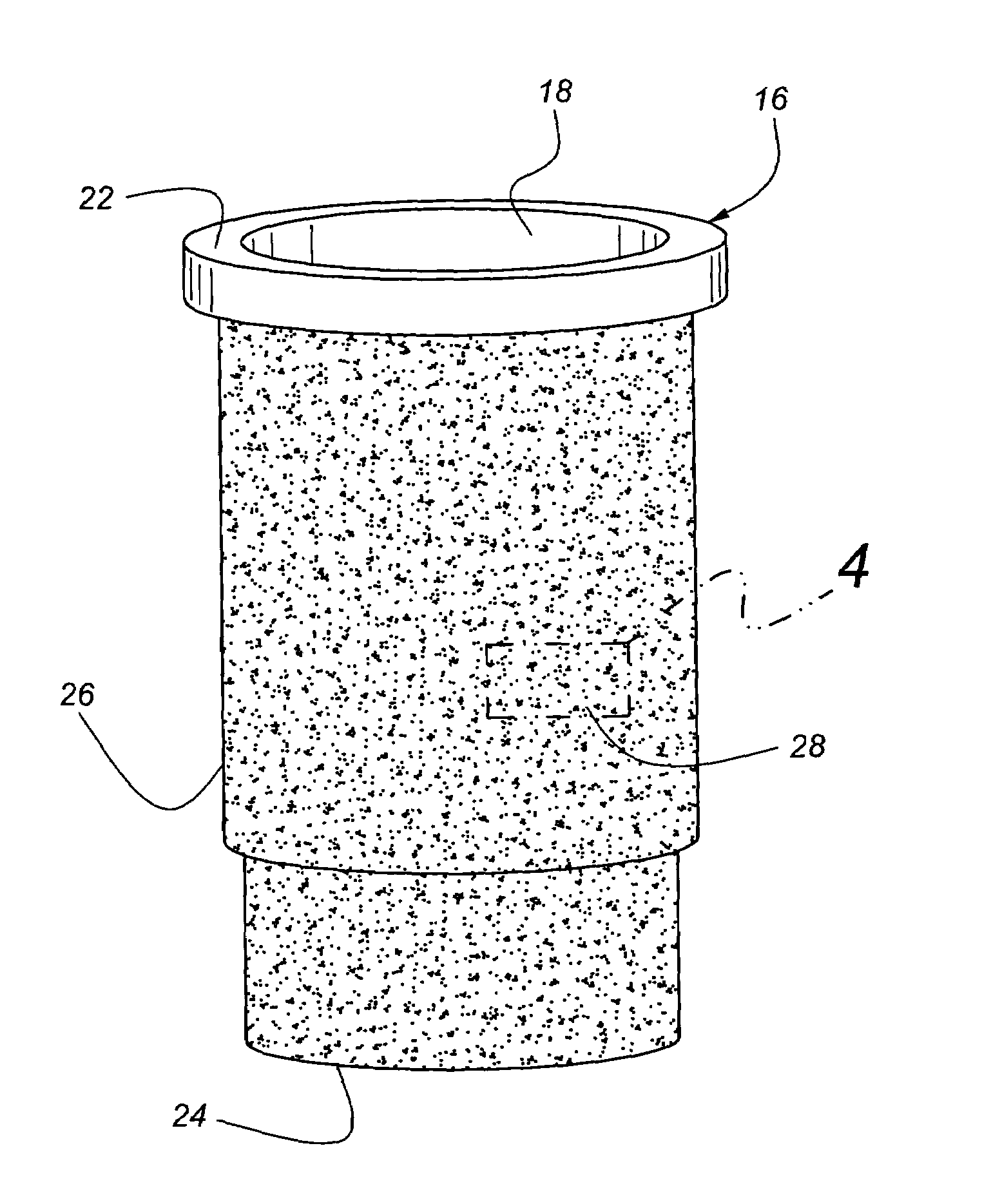
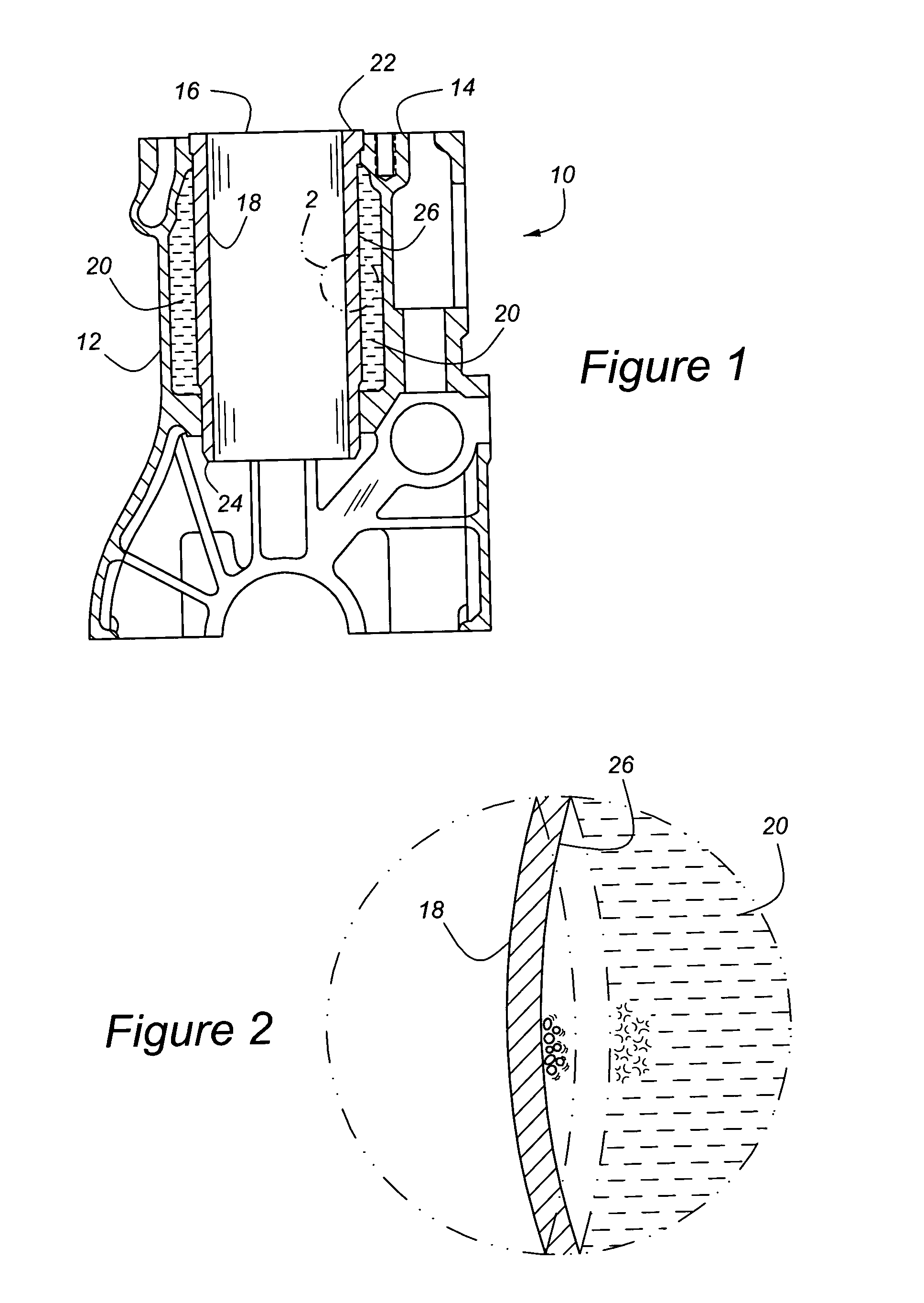
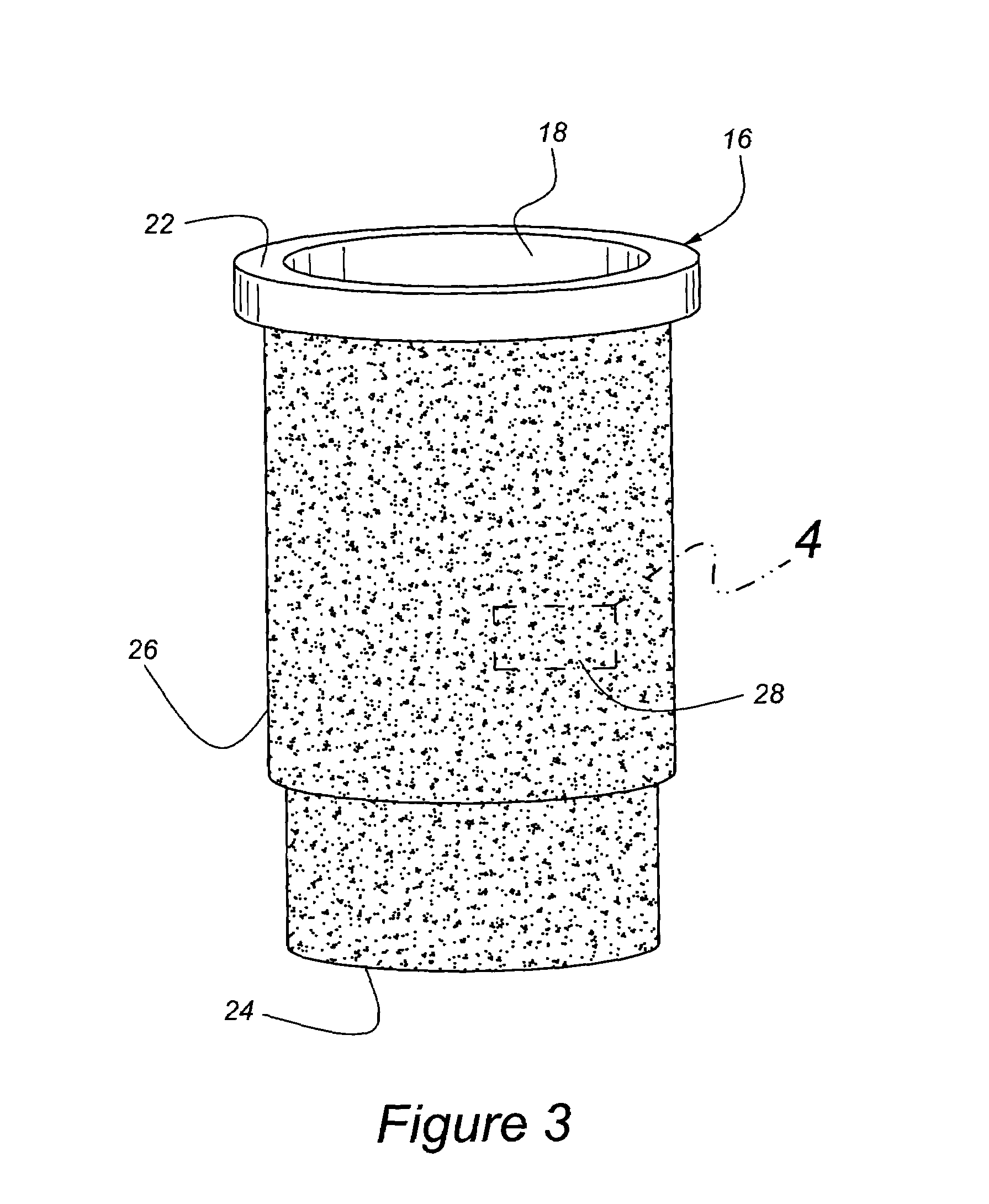
[0022]Referring to the Figures wherein like numerals indicate like or corresponding parts throughout the several views, a liquid-cooled cylinder block for an internal combustion engine is generally shown at 10 in FIG. 1. The cylinder block 10 is largely composed of a crank case 12 typically cast from iron or aluminum. The crank case 12 includes a head surface 14 adapted to receive a head gasket (not shown). A cylinder liner, generally indicated at 16, is fitted into the crank case 12 so that, when fully assembled, a reciprocating piston (not shown) can slide within a generally cylindrical bore 18 and form a portion of the chamber in which the thermal energy of a combustion process is converted into mechanical energy. An intentional space between the cylinder liner 16 and the crank case 12 forms a coolant flow passage 20 through which a liquid cooling medium is circulated for the purpose of removing heat energy from the cylinder liner 16. The cylinder liner 16 is defined by a tubular...


PUM


Abstract

A wet-style cylinder liner (16) for a diesel engine is provided with a surface texture (28) to combat the effects of cavitation-induced erosion. The surface texture (28) can be formed as a coating (30) of manganese phosphate applied about the outer surface (26) of the cylinder liner (16) within the coolant flow passage (20) of the engine. The manganese phosphate is applied in such a manner that a crystalline structure of 2–8 μm average grain size, blocky in nature, clearly faceted, with no cauliflower-like formations and a discernable channel network surrounding the crystals is formed. This crystalline structure works with the natural adhesion and surface tension effects within the liquid coolant to create a stagnant fluid layer about the outer surface (26) of the cylinder liner (16). The stagnant fluid layer functions like a self-healing armor plate. When rapid flexing of the cylinder liner (16) produces cavitation bubbles, these bubbles are held at a distance from the outer surface (26) by the stagnant fluid layer. As the bubbles implode, their kinetic energy is dissipated within the stagnant fluid layer instead of directly upon the outer surface (26) of the cylinder liner (16). The manganese phosphate coating (30) acts as a labyrinth to anchor water molecules, or the engine coolant, and thus promote formation of the stagnant fluid layer.

Description

CROSS-REFERENCE TO RELATED APPLICATIONS[0001]This application claims priority to U.S. Provisional Application No. 60 / 609,906 filed Sep. 14, 2004.BACKGROUND OF THE INVENTION[0002]1. Technical Field[0003]The subject invention relates to a cylinder liner for a diesel engine of the type forming a combustion chamber in cooperation with a reciprocating piston, and more particularly to a diesel cylinder liner having a surface treatment designed to overcome the destructive effects of cavitation-induced erosion.[0004]2. Related Art[0005]Most heavy-duty diesel engines have wet sleeve cylinder liners which allow coolant to circulate on the outside of the cylinders to effectively dissipate heat. These wet sleeve liners are susceptible to a failure mechanism known as cavitation erosion.[0006]Cavitation is a localized low-pressure zone that forms along the outer wall of a cylinder liner. It is caused by the flexing of the cylinder wall due to the high cylinder pressures experienced in diesel engi...

Claims


Application Information

Patent Timeline
Patent Type & Authority Patents(United States)
IPC IPC(8): F02F1/10
CPCF02F1/12F02F1/16F02F3/00
Inventor AZEVEDO, MIGUEL
Owner FEDERAL MOGUL WORLD WIDE LLC
Learn More