
Ultrasonic probe and manufacturing method thereof

a manufacturing method and ultrasonic probe technology, applied in ultrasonic/sonic/infrasonic diagnostics, mechanical vibration separation, applications, etc., can solve problems such as significant loss of sensitivity, transducer elements, and electrical connection with regard to a plurality of electrode layers, and achieve excellent performance, simplify manufacturing, and advantageous enhancement of electrical performance.

Inactive Publication Date: 2006-12-12
ALOKA CO LTD
View PDF19 Cites 29 Cited by
  • Summary
  • Abstract
  • Description
  • Claims
  • Application Information

AI Technical Summary

Benefits of technology

[0008]An advantage of the present invention is that it provides an ultrasonic probe having a layered array transducer with excellent performance and a method of manufacturing such an ultrasonic probe.
[0009]Another advantage of the present invention is that it simplifies manufacture of an ultrasonic probe having a layered array transducer.
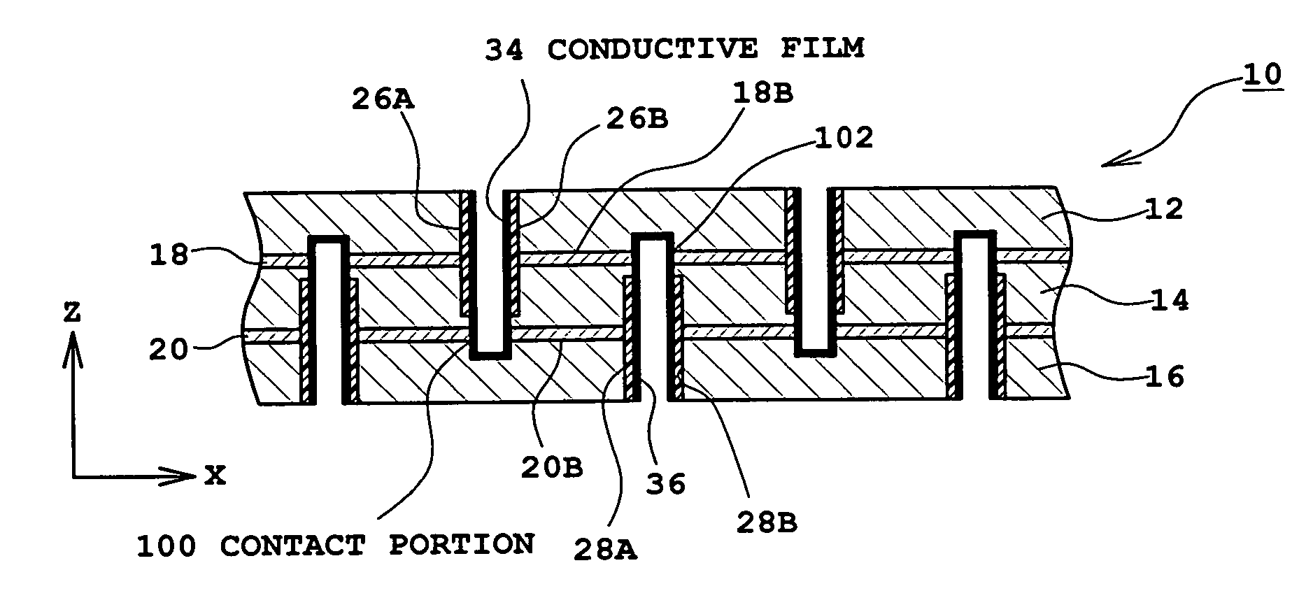
[0010](1) In accordance with one aspect of the present invention, there is provided an ultrasonic probe comprising a layered ultrasonic transducer having a first part and a second part which are adjacent to each other, wherein each of the first part and the second part includes a plurality of first horizontal electrode layers and a plurality of second horizontal electrode layers alternately provided in the vertical direction; a first vertical electrode layer electrically connected with the plurality of first horizontal electrode layers; and a second vertical electrode layer electrically connected with the plurality of second horizontal electrode layers, the first vertical electrode layer included in the first part and the first vertical electrode layer included in the second part being adjacent to each other via a first gap region and having the same polarity, and the ultrasonic transducer includes a first specified structure formed by the first vertical electrode layer included in the first part, the first vertical electrode layer included in the second part, and the first gap region.
[0011]With the above structure, the ultrasonic transducer is a 1D array transducer, a 1.5D array transducer, a 2D array transducer or the like. The first part and the second part, each having a layered structure, are adjacent to each other in the horizontal direction. Namely, the first and second parts correspond to two adjacent layered transducer elements or two segments or blocks interconnected in the horizontal direction in a certain layered transducer element. The first specified structure is formed across (or between) the first and second parts. The first specified structure has a function of connecting a ground line or a signal line to a plurality of first horizontal electrode layers included in the first and second parts. The first specified structure comprises a pair of first vertical electrode layers (the first vertical electrode layer of the first part and the first vertical electrode layer of the second part) which face each other with a space interposed therebetween. Because the pair of the first vertical electrode layers have the same polarity (ground or signal), electrical performance such as insulation property can be advantageously enhanced. A reinforcing layer, an insulating layer, a resin layer used for compounding, an element separation layer, or the like may be provided in the first gap region. Each vertical electrode layer functions as a side electrode, an inner electrode, or the like. While it is desirable to form each vertical electrode layer in the form of a plane, other forms may also be adopted. The array transducer may have a convex shape. In this case, for each transducer element, the vertical direction is defined as the ultrasound propagation direction.
[0012]Preferably, the above ultrasonic transducer further comprises a third part adjacent to the second part, the third part including a plurality of first horizontal electrode layers and a plurality of second horizontal electrode layers alternately provided in the vertical direction; a first vertical electrode layer electrically connected with the plurality of first horizontal electrode layers; and a second vertical electrode layer electrically connected with the plurality of second horizontal electrode layers, the second vertical electrode layer included in the second part and the second vertical electrode layer included in the third part being adjacent to each other via a second gap region and having the same polarity, and the ultrasonic transducer includes a second specified structure formed by the second vertical electrode layer included in the second part, the second vertical electrode layer included in the third part, and the second gap region.
[0013]With the above structure, the first part, the second part, and the third part are arranged in the horizontal direction. The first specified structure is formed across (or between) the first and second parts, and the second specified structure is formed across (or between) the second and third parts. The first specified structure and the second specified structure have different polarities. In the second specified structure, similar to the first specified structure, a pair of the second vertical electrode layers having the same polarity face each other via the second gap region.

Problems solved by technology

This causes significant loss of sensitivity.
The layered transducer elements as described above, however, have a problem of electrical connection with regard to a plurality of electrode layers, in particular, a problem of how a lead or the electrode layer is connected to a plurality of inner electrode layers.
This method, however, also has a problem that because the area of the transducer element is very small, applying any process to a completed transducer element is difficult in terms of manufacturing and is not practical.

Method used


Image

  • Ultrasonic probe and manufacturing method thereof
  • Ultrasonic probe and manufacturing method thereof
  • Ultrasonic probe and manufacturing method thereof

Examples


Embodiment Construction

[0066]Preferred embodiments of the present invention will be described in further detail with reference to the accompanying drawings.

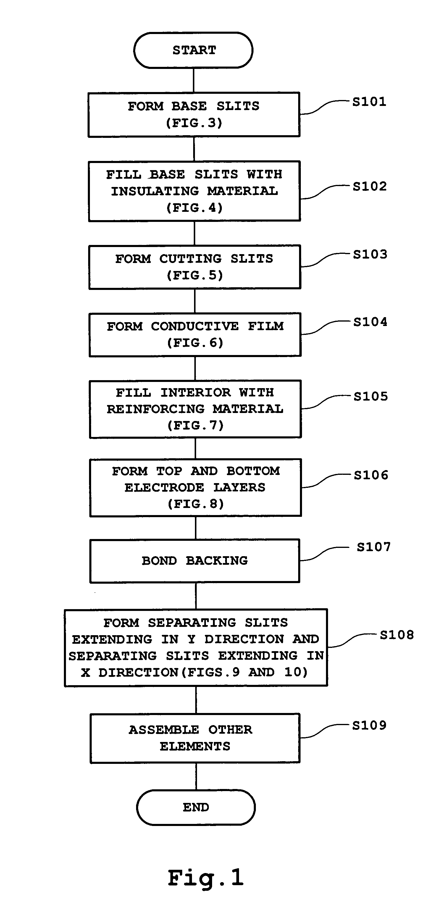
[0067]FIG. 1 shows one example manufacturing process for an ultrasonic probe in the form of flow chart. This ultrasonic probe is a probe connected via a probe cable to an ultrasonic diagnosis apparatus which provides ultrasonic diagnosis of a living body and captures echo data by ultrasound transmission / reception. The ultrasonic probe may be used in contact with a surface of a living body or may be inserted into a body cavity of a living body. A manufacturing process of such an ultrasonic probe will be described, along with the structural features of the ultrasonic probe (particularly of an array transducer).

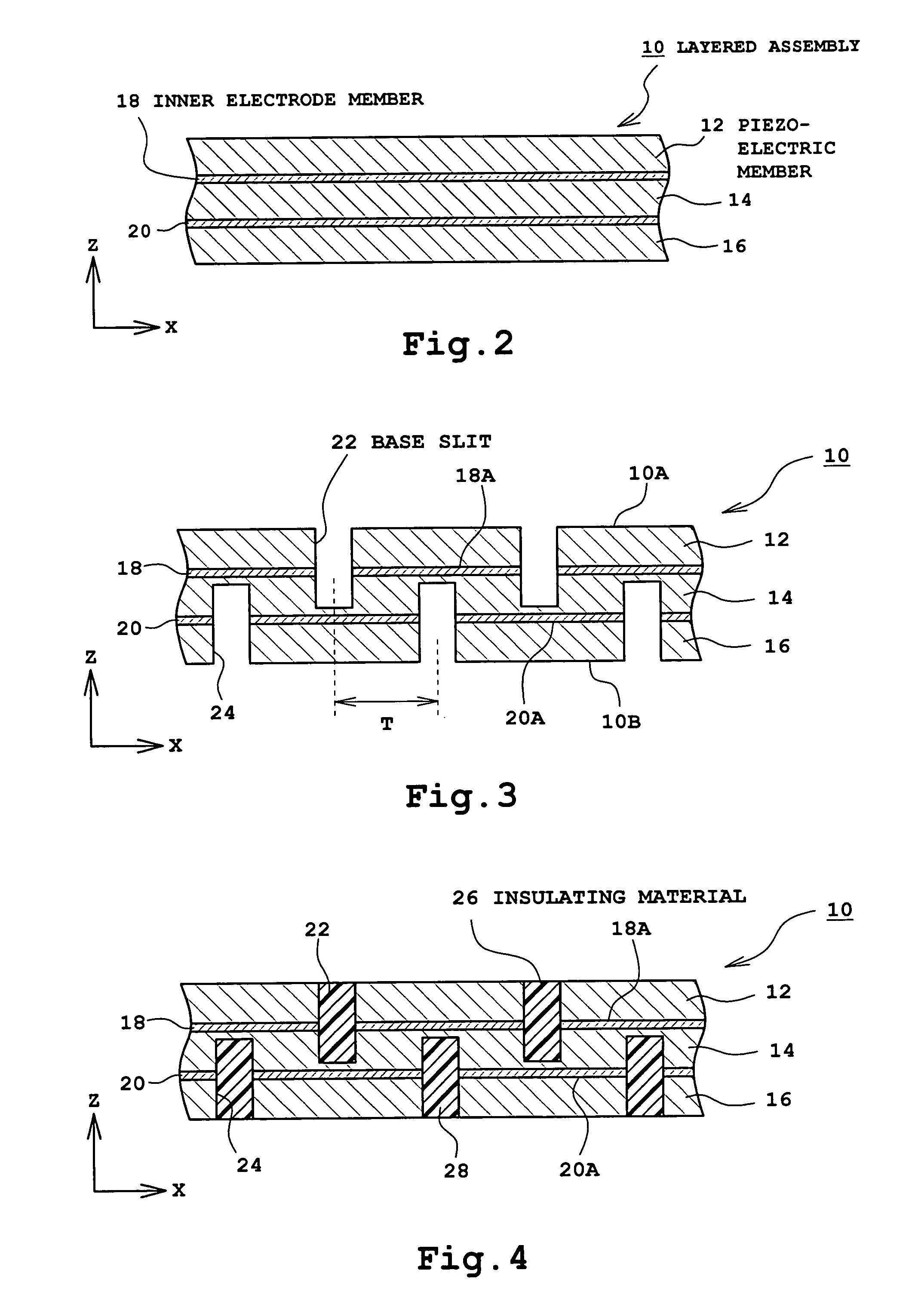
[0068]Prior to step S101 of FIG. 1, a laminated unit (a layered assembly) to which polarization has been applied as shown in FIG. 2 is provided. A plurality of members forming the layered assembly are previously bonded to each other. More specifica...


PUM

PropertyMeasurementUnit
sizeaaaaaaaaaa
sizeaaaaaaaaaa
depth L1aaaaaaaaaa

Abstract

An ultrasonic probe for use in an ultrasonic diagnosis apparatus for a living body comprises an array transducer made up of a plurality of layered transducer elements. A specified structure (face-to-face structure) is created across two adjacent transducer elements. In each transducer element, a first vertical electrode layer for ground is connected with a top electrode layer and an inner electrode layer, and a second vertical electrode layer for signal is connected with a bottom electrode layer and an inner electrode layer. When creating the specified structure, steps including formation of slits in a layered assembly and filling of the slits or the like are repeated. By finally forming a plurality of separating slits, the layered assembly is divided into a plurality of transducer elements. On the other hand, each transducer element is compounded in the horizontal direction. The compounding is performed at any stage of before, during or after formation of the specified structure.

Description

BACKGROUND OF THE INVENTION[0001]1. Field of the Invention[0002]The present invention relates to an ultrasonic probe and a method of manufacturing an ultrasonic probe, and more particularly to a structure of a layered array transducer for use in ultrasonic diagnosis of a living body and a method of manufacturing the same.[0003]2. Description of Related Art[0004]2D array transducers (including sparse 2D array transducers) and 1.5D array transducers are known as array transducers having a plurality of transducer elements arranged in an array. In these array transducers, because the size of each transducer element forming an array transducer is very small, the electrical impedance of each transducer element is very high and this prohibits electrical impedance match between each transducer element and a cable (or an apparatus body). This causes significant loss of sensitivity.[0005]In order to deal with the above problem, a technique of forming each transducer element into a layered str...

Claims


Application Information

Patent Timeline
Patent Type & Authority Patents(United States)
IPC IPC(8): H01L41/107A61B8/00H01L41/083B06B1/06H01L41/22H01L41/338H01L41/37
CPCB06B1/064H01L41/37H01L41/183H01L41/338Y10T29/4908Y10T29/4902Y10T29/49798Y10T29/49005Y10T29/42A61B8/4494H10N30/852H10N30/088H10N30/092
Inventor SATO, SHOHEI
Owner ALOKA CO LTD
Learn More