Eureka AIR delivers breakthrough ideas for toughest innovation challenges, trusted by R&D personnel around the world.

Apparatus for recording information in and/or reproducing information from a ferroelectric recording medium

a dielectric recording medium and dielectric recording technology, applied in mechanical recording, nanoinformatics, instruments, etc., can solve the problems of limited recording density, methods with limitations of recording density, and limited recording density, and achieve the effect of increasing the recording/reproducing ra

Inactive Publication Date: 2006-12-12
PIONEER CORP +1
View PDF16 Cites 38 Cited by
  • Summary
  • Abstract
  • Description
  • Claims
  • Application Information

AI Technical Summary

Benefits of technology

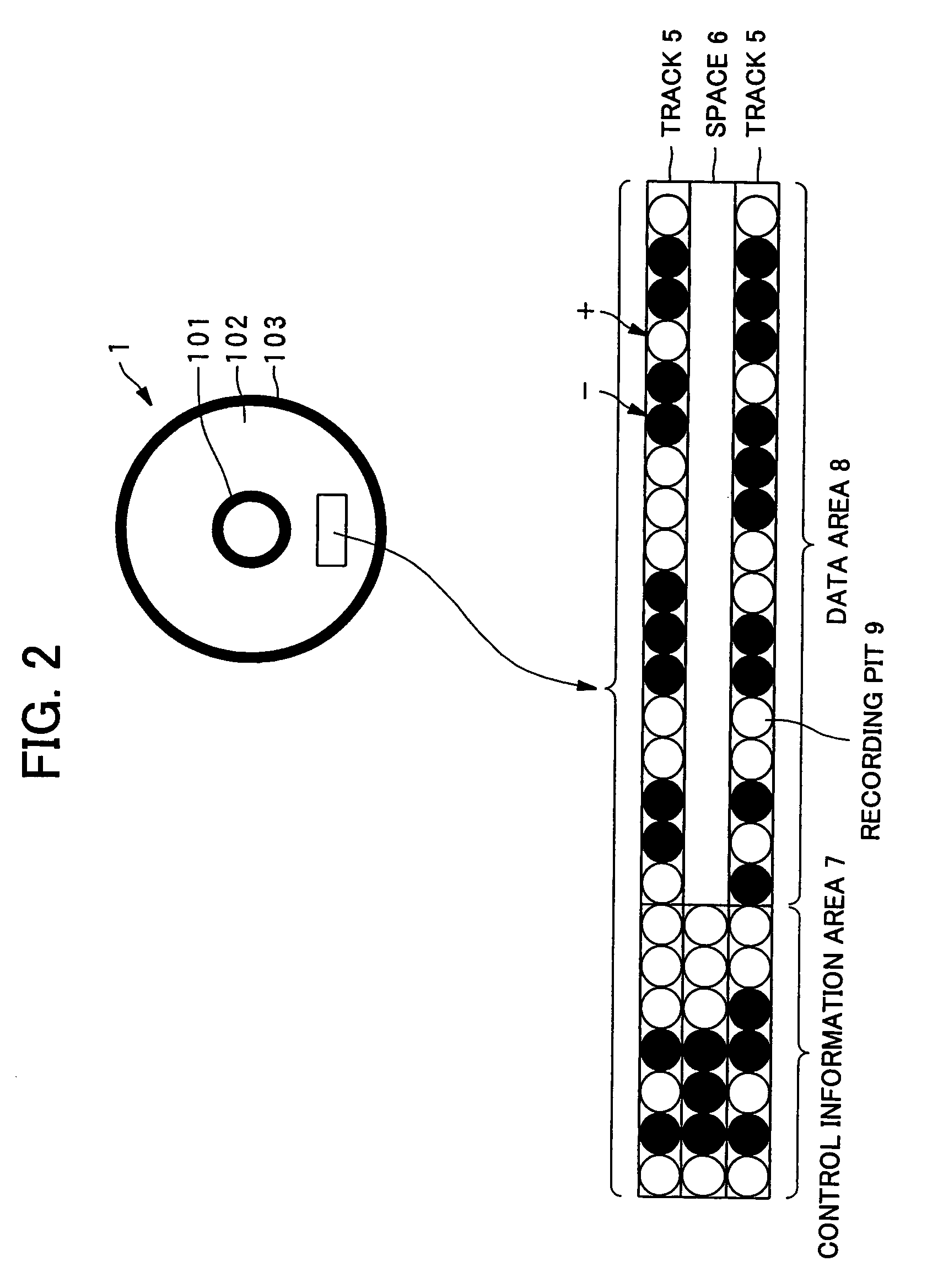
[0013]In recording data in the dielectric recording medium, the data is recorded by changing the polarization directions in such a condition that the polarization directions of the dielectric material correspond to the bits of the data (e.g. “1”, “0”). If the polarization direction corresponding to one bit condition of data (e.g. “1”) is the same as the initial polarization direction, it is not necessary to change the polarization direction to record the bit of data. If the polarization direction corresponding to the other bit condition of data (e.g. “0”) is the opposite direction to the initial polarization direction, it is necessary to change the polarization direction to record the bit of data. In the case that the polarization directions of the dielectric material within the data area are initially set in one direction, the polarization directions within all of the data area, except portions where the data is already recorded by changing the polarization direction, maintain the initial uniform polarization direction. Therefore, since there are no disordered polarization directions within the data area, it is possible to read the data recorded in the dielectric material without noise, so that the S / N ratio of a reproduction signal improves. Thus, it is possible to record / reproduce information, such as control information for tracking control and for address search, with a high S / N ratio. Therefore, even in super-high-density recording, it is also possible to perform control, such as tracking control and address search control, with a relatively high accuracy.
[0031]According to this aspect, LiTaO3 may be used as a medium material, in which it is easy to reverse the polarization even by applying an electric field with a probe because of its low dielectric constant. It may be easily formed to be the dielectric recording medium by a predetermined method so that the recording is performed with respect to the Z surface of the LiTaO3, where a plus surface and a minus surface of the polarization are in a 180-degree domain relationship.
[0056]According to this aspect, it is possible to simultaneously perform recording / reproducing operation to the plurality of recording tracks, which increases a recording / reproducing rate.

Problems solved by technology

However, the inertia of the pickup is relatively large, which is not appropriate for high-speed reading, and the size of the recording pit in using a focusing optical system, such as lens, is defined by the diffraction limit of light, so that its recording density is limited to 50 G bit / inch2.
However, the recording density is limited to 1 T bit / inch2 due to thermal fluctuation of magnetic recording information and the presence of a Bloch wall in a code reverse or sign change portion, even if patterned media are used considering the above cause.
However, these methods have the limitations of the recording density, which is between 500 G and 1 T bit / inch2, due to intervening heat conduction.
However, with respect to dielectric recording / reproducing using the above-described SNDM, specific methods have not been presented for tracking control, address search control, and the like.

Method used


Image

  • Apparatus for recording information in and/or reproducing information from a ferroelectric recording medium
  • Apparatus for recording information in and/or reproducing information from a ferroelectric recording medium
  • Apparatus for recording information in and/or reproducing information from a ferroelectric recording medium

Examples


Embodiment Construction

(Embodiment of Dielectric Recording Medium)

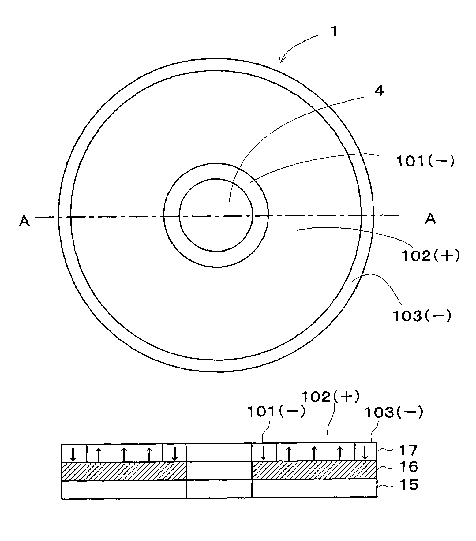
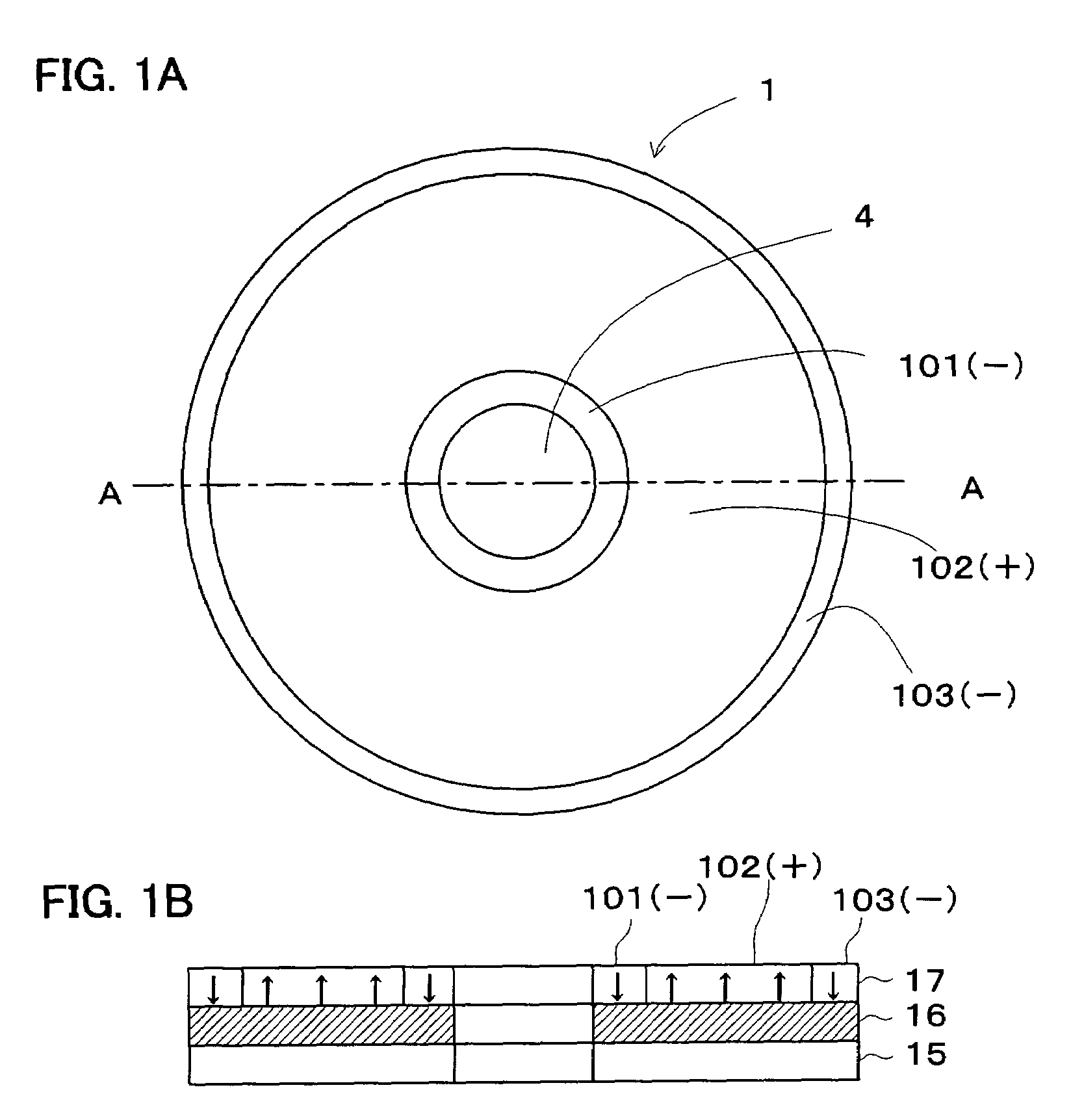
[0071]The embodiment of a dielectric recording medium associated with the present invention will be explained. As shown in FIG. 1A, a ferroelectric recording medium 1 is one example of a dielectric recording medium. The ferroelectric recording medium 1 is in the shape of a disc. The ferroelectric recording medium 1 is provided with: a center hole 4; an inner area 101; a recording area 102; and an outer area 103, arranged concentrically from the inside in this order. The center hole 4 is used when attaching the ferroelectric recording medium 1 to a spindle motor or the like.

[0072]The inner area 101, the recording area 102 and the outer area 103 are formed in a surface of or a layer in the ferroelectric recording medium 1 made of a uniform and flat ferroelectric material. The recording area 102 has an up polarization direction, i.e. being a plus surface. In this case, the inner area 101 and the outer area 103 have down polarization direction,...


PUM


Abstract

A dielectric recording medium in a disc form is provided with: a center hole; an inner area; a recording area; and an outer area, arranged concentrically from the inside in this order. The inner area, the recording area, and the outer area contain a uniform and flat dielectric material and are polarized with the polarization direction of the recording area opposite to that of the inner area and the outer area in their initial condition. The recording area in which data is recorded has tracks and spaces, each of which is between two of the tracks, and is provided with areas in which control information about the recording / reproducing is recorded, in the track and the space.

Description

BACKGROUND OF THE INVENTION[0001]1. Field of the Invention[0002]The present invention relates to a dielectric recording medium and a dielectric recording / reproducing apparatus for recording information with high density in microdomains in a dielectric substance, especially in a ferroelectric substance, and reproducing information recorded in it.[0003]2. Description of the Related Art[0004]As conventional techniques associated with high-density information recording / reproducing, there are proposed optical recording, magnetic recording, thermal recording, ferroelectric recording and the like.[0005]In the optical recording, an optical pickup with a laser as a light source is used. Data is recorded by forming pits that are concave-convex on a disk surface or forming the crystal phase of a phase shift medium. The recorded data is reproduced by using the difference in the reflectance of amorphous phases or using the magneto optical effect. However, the inertia of the pickup is relatively ...

Claims


Application Information

Patent Timeline
IPC IPC(8): G11B3/70G11B9/00G11B9/02G11B9/06G11B9/07G11B9/14G11B11/00G11B11/08
CPCB82Y10/00G11B9/02G11B9/06G11B9/061G11B9/062G11B9/14G11B9/1409G11B9/1418G11B9/1427G11B9/1454G11B9/1472G11B9/1481G11B11/007G11B11/08
Inventor ONOE, ATSUSHICHO, YASUO
Owner PIONEER CORP
Why Eureka
Eureka Blog
Learn More