Permanent magnet rotating electric machine and electric car using the same
a permanent magnet and electric machine technology, applied in the direction of magnetic circuit rotating parts, propulsion by batteries/cells, magnetic circuit shape/form/construction, etc., can solve the problems of high-speed region iron loss, increase fuel expenses of the car, etc., and achieve high efficiency, reduced fuel expenses, and reduced iron loss
- Summary
- Abstract
- Description
- Claims
- Application Information
AI Technical Summary
Benefits of technology
Problems solved by technology
Method used
Image
Examples
first embodiment
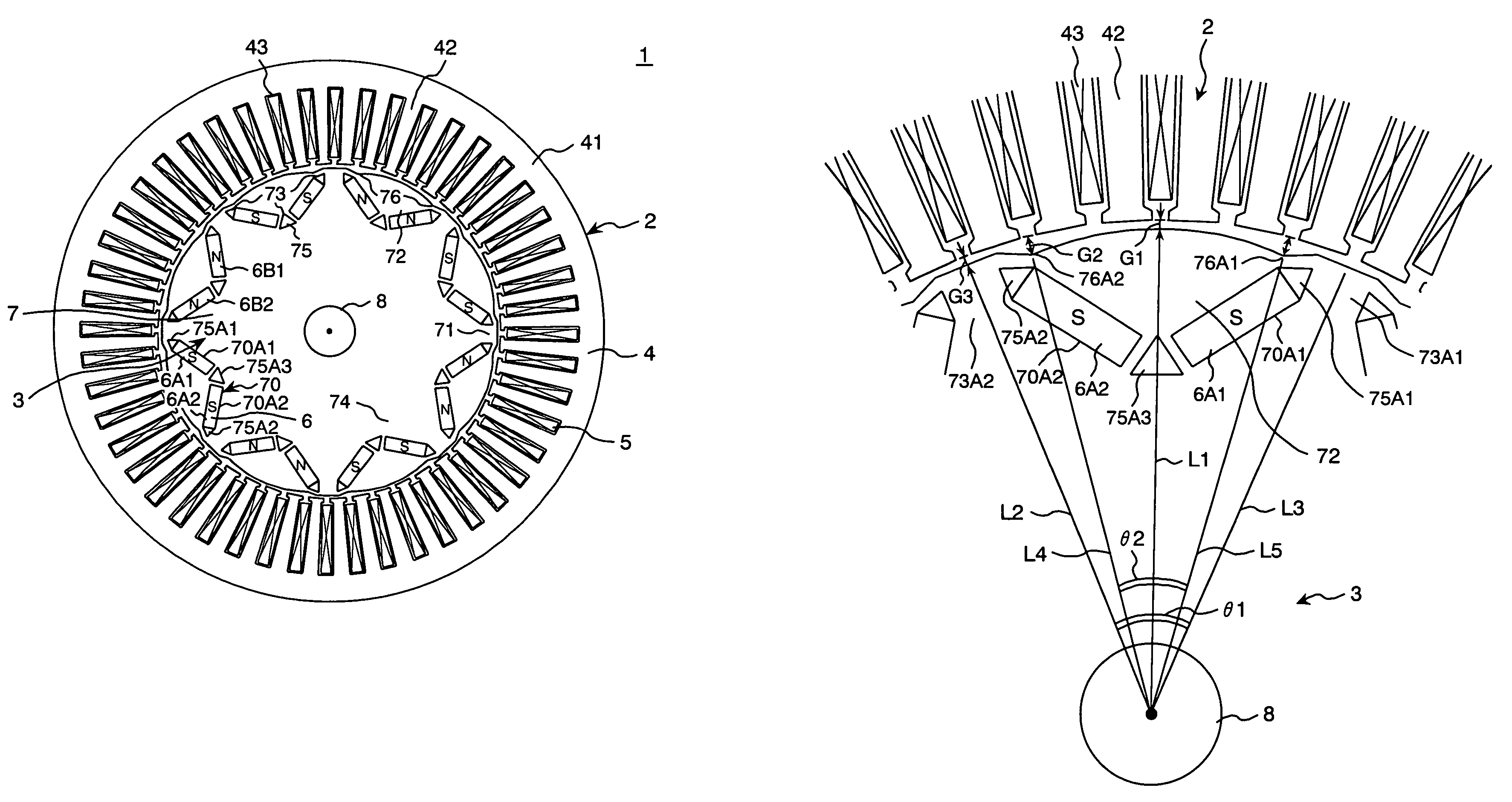
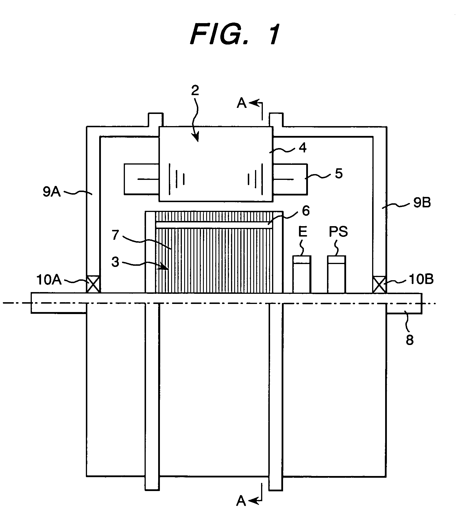
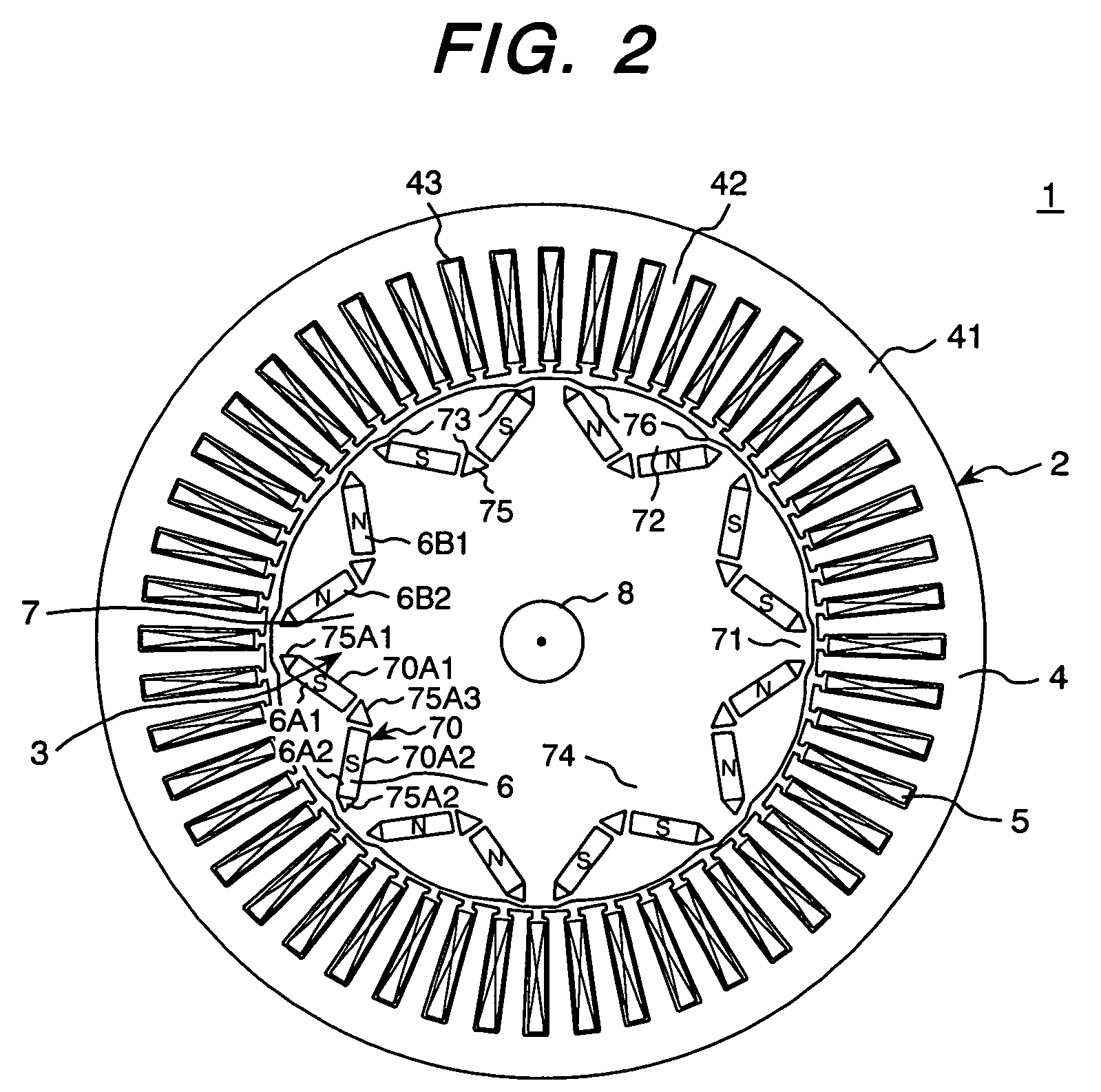
[0034]FIGS. 1 and 2 are cross sectional views showing the constitution of the permanent magnet rotating electric machine of the present invention. FIG. 1 is a cross sectional view in the parallel direction with the rotation axis and FIG. 2 is a cross sectional view in the perpendicular direction to the rotation axis and a view in the A—A direction shown in FIG. 1. Further, in FIGS. 1 and 2, the same numerals indicate the same parts.
[0035]As shown in FIG. 1, a permanent magnet rotating electric machine 1 includes a stator 2, a rotor 3, and end brackets 9A and 9B. The stator 2 has a stator iron core 4 and stator windings 5. The rotor 3 has a rotor iron core 7 composed of a magnetic substance and a shaft 8. Further, the rotor 3, via the shaft 8 fit into the rotor iron core 7, is rotatably held by bearings 10A and 10B fit into the end brackets 9A and 9B. Further, the constitution shown in the drawing has no frame on the outer periphery of the stator iron core 4. However, a frame may be ...
second embodiment
[0064]Next, by referring to FIG. 7, the constitution of the permanent magnet rotating electric machine of the present invention will be explained. Here, the whole constitution of the permanent magnet rotating electric machine of this embodiment is the same as that shown in FIG. 1.
[0065]FIG. 7 is a cross sectional view showing the constitution of the permanent magnet rotating electric machine of the second embodiment of the present invention. FIG. 7, similarly to FIG. 2, is a cross sectional view in the direction perpendicular to the rotation axis and a view in the direction of A—A. Further, the same numerals as those shown in FIGS. 1 and 2 indicate the same parts.
[0066]In the constitution shown in FIG. 2, 2 permanent magnets constitute one magnetic pole of the rotor and are arranged in a V shape, while in this embodiment, as shown in FIG. 7, one permanent magnet 6J constitutes one magnetic pole of the rotor and is inserted into an insertion hole 70J in which the long sides of the se...
third embodiment
[0071]Next, by referring to FIGS. 8 to 10, the constitution of the permanent magnet rotating electric machine of the present invention will be explained. Here, the whole constitution of the permanent magnet rotating electric machine of this embodiment is the same as that shown in FIG. 1.
[0072]FIG. 8 is a cross sectional view showing the constitution of the permanent magnet rotating electric machine of the third embodiment of the present invention. FIG. 8, similarly to FIG. 2, is a cross sectional view in the direction perpendicular to the rotation axis and a view in the direction of A-A. Further, the same numerals as those shown in FIGS. 1 and 2 indicate the same parts.
[0073]In this embodiment, on the outer peripheral part of the magnetic pole pieces 72 of the rotor 3 of the permanent magnet rotating electric machine 1, at the position of θ4 from the center of the magnetic poles, concavities 77 are installed. The other constitution is the same as that shown in FIG. 2. However, the c...
PUM
 Abstract
Description
Claims
Application Information
 - R&D
- Intellectual Property
- Life Sciences
- Materials
- Tech Scout
- Unparalleled Data Quality
- Higher Quality Content
- 60% Fewer Hallucinations
Browse by: Latest US Patents, China's latest patents, Technical Efficacy Thesaurus, Application Domain, Technology Topic, Popular Technical Reports.
© 2025 PatSnap. All rights reserved.Legal|Privacy policy|Modern Slavery Act Transparency Statement|Sitemap|About US| Contact US: help@patsnap.com


