Apparatus and method for forwarding data on multiple label-switched data paths

a technology of data path and data forwarding, applied in the direction of electrical apparatus, data switching network, digital transmission, etc., can solve the problems of difficult to compute the hash of ip address at each node, difficult to distinguish multiple physical parallel links within the route or path, etc., to save considerable processing time, fast and more efficient, and efficient use

Inactive Publication Date: 2006-12-19
PLURIS
View PDF13 Cites 47 Cited by
  • Summary
  • Abstract
  • Description
  • Claims
  • Application Information

AI Technical Summary

Benefits of technology

[0011]The data for each source / destination pair will be assigned a single path within the route. As a result, misalignment of data at the egress node is avoided.
[0015]The approach of the invention provides numerous advantages. For example, label switching, which is much faster and more efficient than IP forwarding, can be used efficiently in an environment with multiple parallel links. The system allows multiple paths to be set up simultaneously instead of requiring that each path be set up individually. This saves considerable processing time, which leads to improved network operation, particularly with respect to reduced time to set up or adjust paths. This also allows a bundled set of paths to be handled with reduced control resources, when compared to the resources required to set up paths individually.

Problems solved by technology

In MPLS, the labels assigned by the nodes identify the route to be taken from node to node along the LSP, but they do not readily provide the ability to distinguish multiple physical parallel links within the route or path.
One reason for this is that it is difficult to compute an IP address hash at each node or “hop,” as is done in IP forwarding, because the IP header is “hidden” behind the MPLS header.
Hence, the hash procedure, which may be usable to select one of many paths, is not readily adaptable to MPLS.
This means that an interior node cannot reliably compute an address hash, because it does not know anything about the contents of the packet behind the first MPLS header.
Furthermore, even if it is known that all packets carry IP datagrams, there is a problem knowing where the IP header is located within the packet.
Conventional MPLS suffers a drawback in that, with conventional MPLS, it is relatively inefficient to set up multiple parallel paths to distribute traffic over multiple parallel physical links.
This signaling becomes particularly inefficient when there are a large number of potential parallel paths.

Method used


Image

  • Apparatus and method for forwarding data on multiple label-switched data paths
  • Apparatus and method for forwarding data on multiple label-switched data paths
  • Apparatus and method for forwarding data on multiple label-switched data paths

Examples


Embodiment Construction

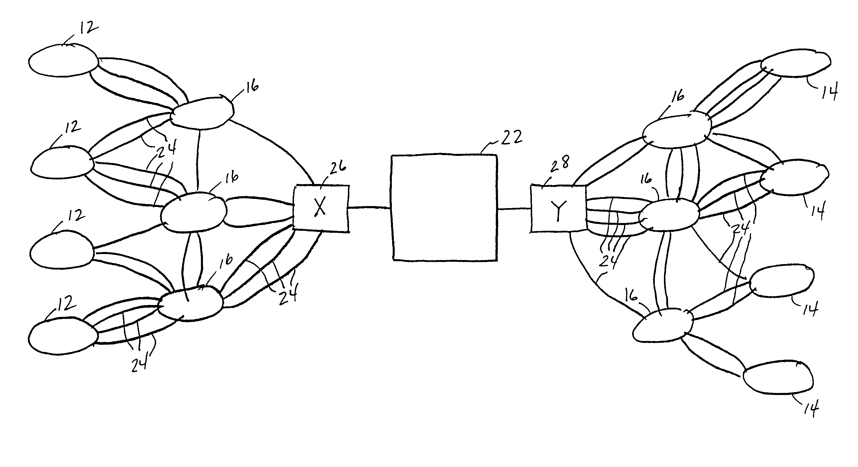
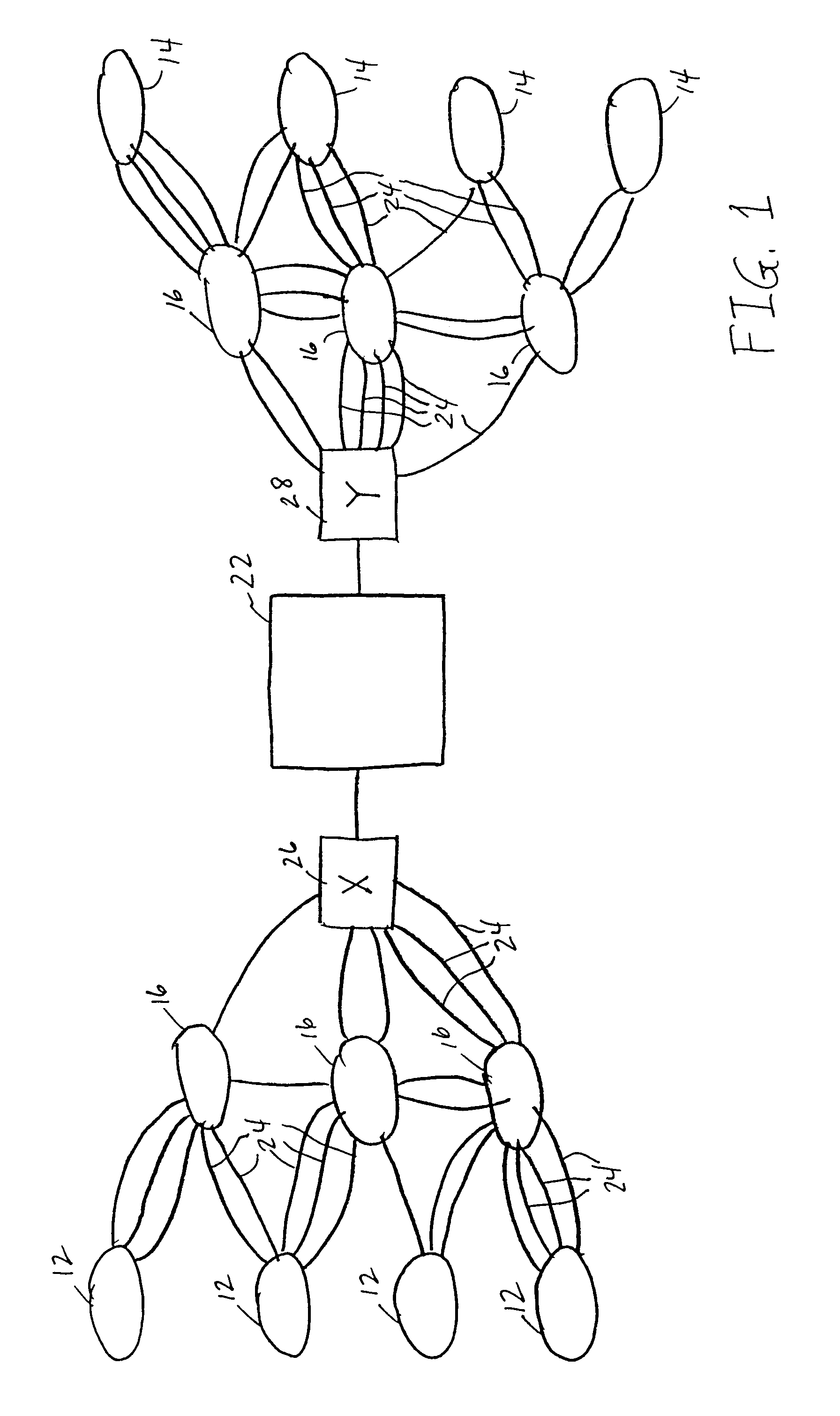
[0020]FIG. 1 is a schematic block diagram of a network 10 which can implement a packet forwarding technique in accordance with one embodiment of the invention. Referring to FIG. 1, the network 10 can include multiple nodes 16 connected by links 24 which carry data packets from node to node on the network 10. As shown, the network includes multiple source nodes 12 and destination nodes 14 connected to the network nodes 16. A source node 12 can forward data packets over the network 10 to a destination node 14. It will be understood that the source and destination nomenclature is used as a convention to describe the direction of data flow. In conventional networks, all nodes can typically serve as a source node or a destination node, depending upon whether it is sending or receiving data.

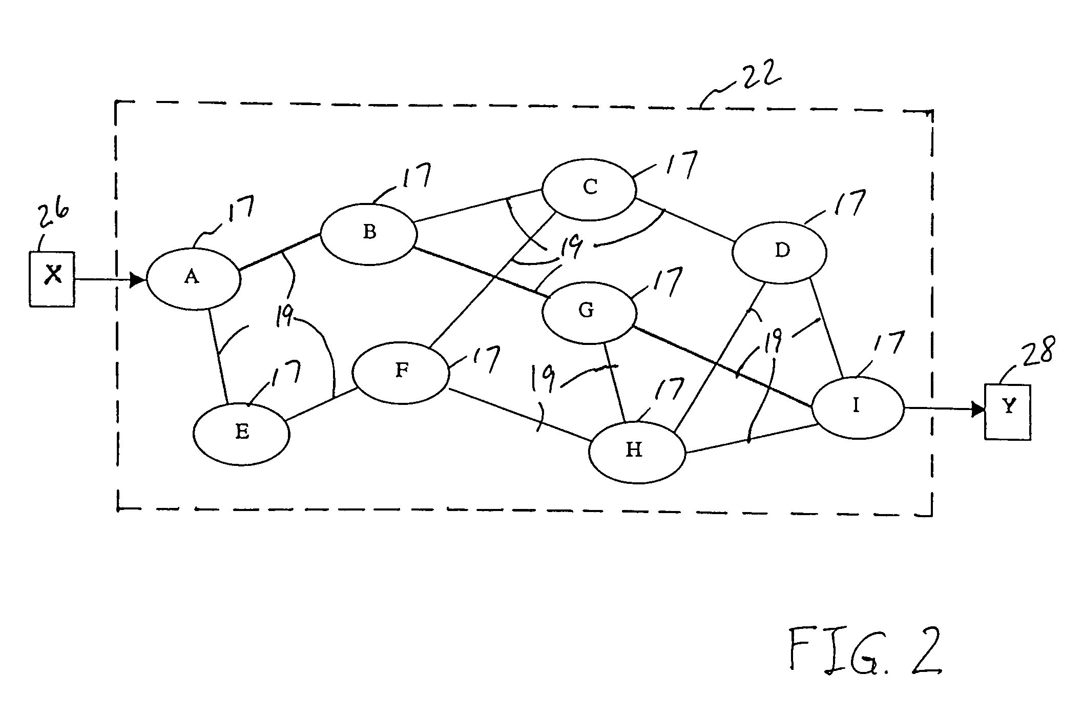
[0021]In accordance with the invention, the network 10 includes a subnetwork 22 over which packets can be transferred en route from a source node 12 to a destination node 14. Packets enter the subnetwo...


PUM


Abstract

An apparatus and method for forwarding data on a network are described. A label-switching subnetwork within the network includes an ingress node and an egress node coupled to source and destination nodes, respectively, on the network. The ingress node sends a signal along a route within the subnetwork through a plurality of subnetwork nodes to the egress node. In response, the subnetwork nodes transmit response signals back along the route toward the ingress node which define the route through the subnetwork and simultaneously allocate a plurality of paths within the route. A single path can be selected for forwarding of data packets associated with a source / destination pair, ensuring that data packets arriving at the destination are not misaligned.

Description

BACKGROUND OF THE INVENTION[0001]In digital computer networks such as the Internet, collections of data, referred to as “datagrams,” are typically transferred from node to node over the network in packets. Each packet of data typically includes a header portion and a data portion. In accordance with the common Internet protocol (IP), the header portion typically includes a 32-bit source identifying portion which identifies the source node that originated the packet and a 32-bit destination identifying portion which identifies the destination node to which the packet is ultimately to be transferred.[0002]At each node, a router is used to forward the packet to the next node in the path toward the destination node. When a router receives a packet, it examines the destination address in the packet header. It then searches its locally stored routing table to determine the next node to which the packet should be transferred in order to ensure that it will reach its destination, typically ...

Claims


Application Information

Patent Timeline
Patent Type & Authority Patents(United States)
IPC IPC(8): H04L12/28H04L12/56
CPCH04L45/00H04L45/26H04L45/50H04L45/243
Inventor RENWICK, JOHN K.CALLON, ROSS W.
Owner PLURIS
Why Eureka
Try Eureka