
Transmitter system for wireless communication with implanted devices

a transmitter system and implanted device technology, applied in the field of digital signal transmission systems, can solve the problems of neurostimulation devices, deterioration of the targeted low power operation of the transmitter circuit, and no transmission device source is availabl

Active Publication Date: 2006-12-19
MEDTRONIC INC
View PDF44 Cites 102 Cited by
  • Summary
  • Abstract
  • Description
  • Claims
  • Application Information

AI Technical Summary

Benefits of technology

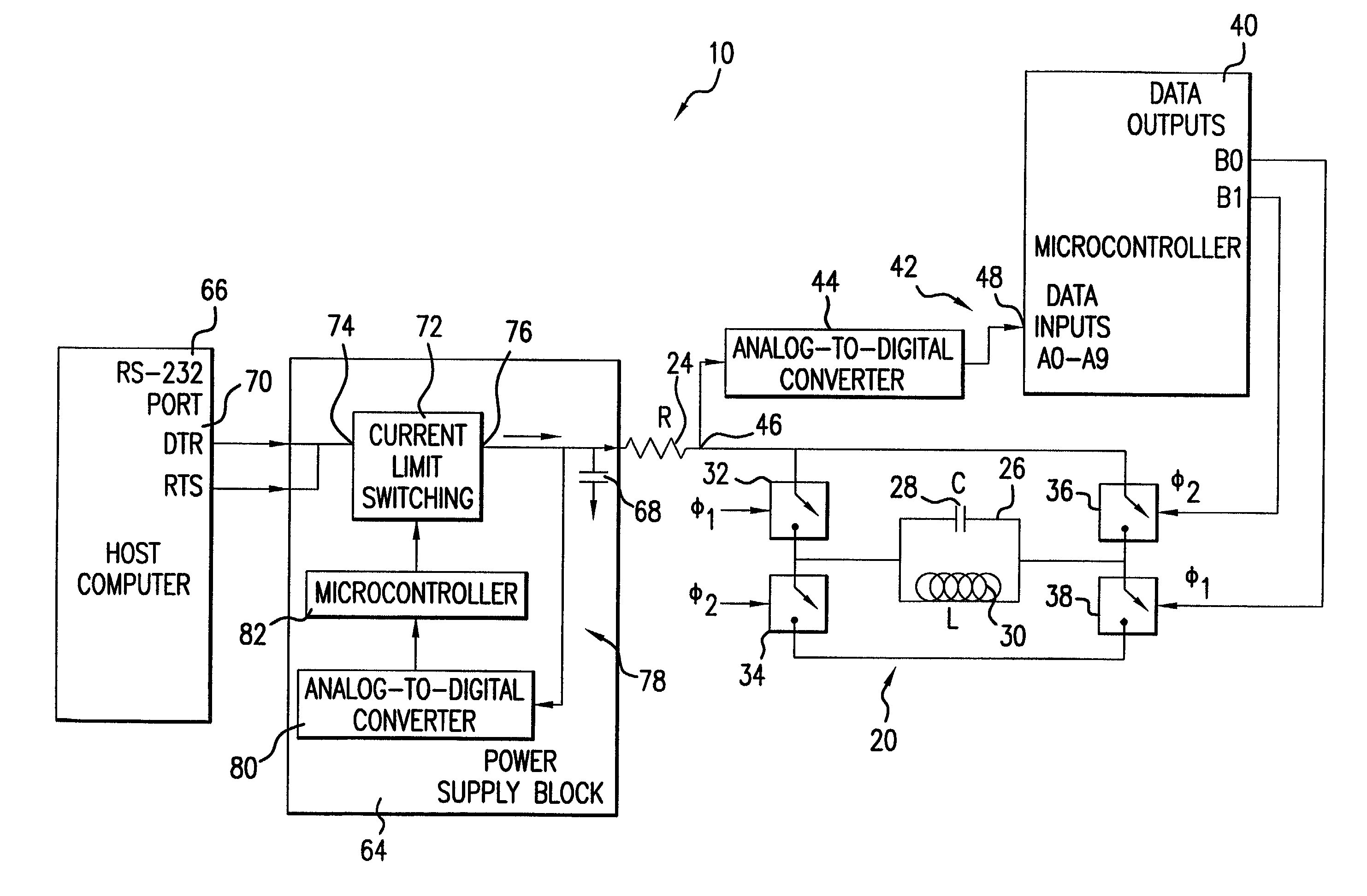
[0010]It is therefore an object of the present invention to provide a battery operated efficient transmitter system for medical data transmission substantially free of the de-tuning effects caused by external influences such as human body capacitance.
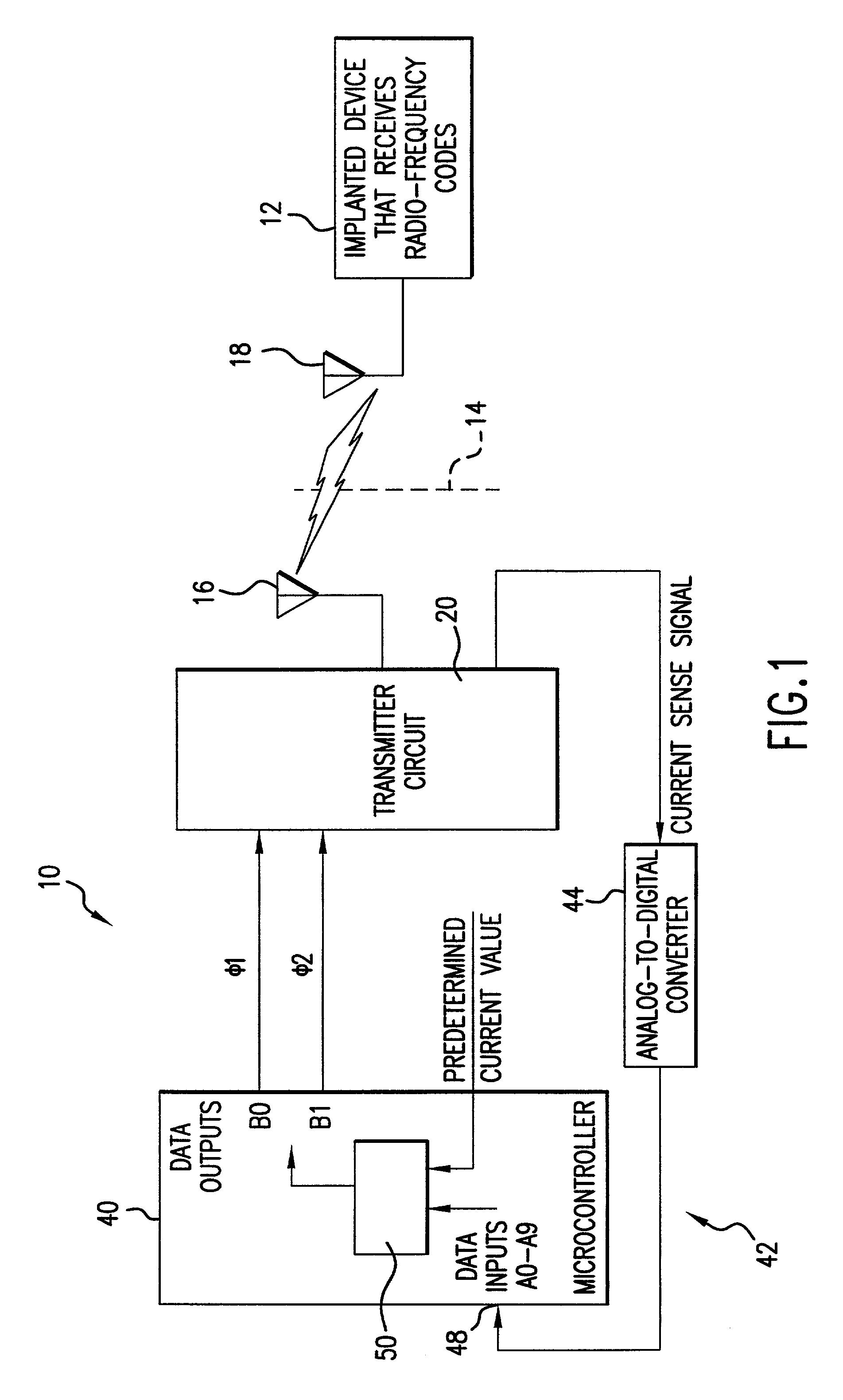
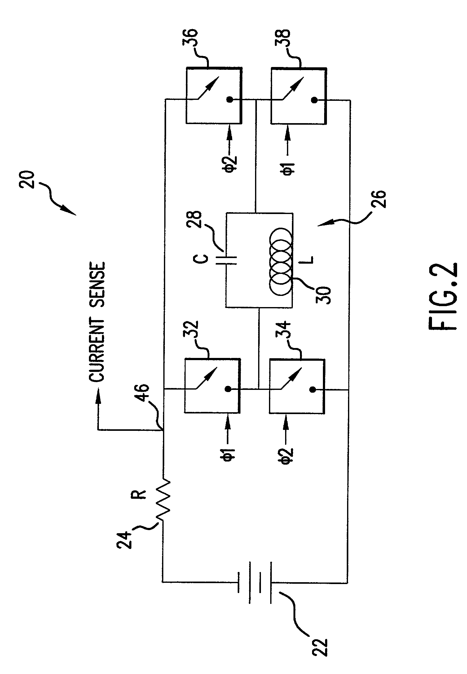
[0011]It is another object of the present invention to provide a battery operated transmitter where efficient low power operation is achieved by providing feedback control of the current consumed by the transmitter circuit in order to adjust resonating frequency of the resonant LC network in the transmitter circuit once the deviation of the consumed current from a predetermined optimal level has been sensed.
[0012]It is another object of the present invention to provide a battery operated transmitter system where the signal indicative of the current consumed by the transmitter circuit is read by an Analog-to-Digital converter. The output of the analog-to-digital converter is coupled to a microcontroller to supply thereto digital data corresponding to the sensed consumed current. In this manner, the microcontroller monitors the data and changes the resonant frequency of the LC network (LC tank and human body), thus reducing the current consumed by the transmitter circuit to a desired pre-set level.
[0013]It is still an object of the present invention to provide a transmitter system for wireless communication with implanted medical devices employing a power supply scheme which includes a high value storage capacitor, and uses a commonly available RS-232 signal of a host computer as a raw power source to charge the storage capacitor to full capacity in the least amount of time with minimal or zero losses of the voltage developed from the RS-232 signal.
[0018]a controller generating and outputting a drive signal to the transmitter circuit to control the resonance frequency thereof. The controller is coupled to the current sensing unit to monitor the sensed current and to change the drive signal to adjust the resonance frequency of the transmitter circuit once the sensed current exceeds a predetermined current value in order to minimize the current consumed by the transmitter circuit.
[0031]Preferably, the microprocessor establishes a switching hysteresis to prevent switch chatter at the crossover points.

Problems solved by technology

However, since some of the transmitters may be placed in close proximity to living tissue during operation, the external influences, such as human body capacitance and loading effects, may tend to de-tune a high-Q resonant LC network in the transmitter circuit, thus deteriorating the targeted low power operation of the transmitter circuit.
Another problem has existed in the field of wireless communication with implanted neurostimulation devices in that portable transmitters often depend upon either wall adapters or host equipment as power sources.
In some cases, however, neither source is available for the transmission device.
Additionally, for the wireless transmitter scheme high current pulses are often needed which exceed the capability of low power supplies such as batteries.

Method used


Image

  • Transmitter system for wireless communication with implanted devices
  • Transmitter system for wireless communication with implanted devices
  • Transmitter system for wireless communication with implanted devices

Examples


Embodiment Construction

[0042]Referring to FIG. 1, a transmitter system 10 of the present invention is positioned externally to an implanted device 12 and is separated therefrom by a barrier 14 which for a particular application of the transmitter system 10 are the tissues and skin of a human body, i.e., of a patient using the implanted device 12. For communication between the transmitter system 10 and the implanted device 12, the transmitter system 10 is provided with an antenna 16 which radiates a carrier signal modulated by an information signal towards antenna 18 of the implanted device 12.

[0043]The implanted device 12 may perform a plurality of functions, including tissue stimulation, sensing and monitoring the body parameters, as well as other parameters. Regardless of the type of function performed by the implanted device 12, it receives coded information, such as on / off switching, frequency and amplitude of stimulation, stimulation pattern, etc., from the transmitter system 10. Typically, transmitt...


PUM


Abstract

A transmitter system for wireless communication with implanted medical devices includes a transmitter circuit having a resonant network the resonant frequency of which is adjusted by a feedback circuit in order to minimize the current drain from the power source and maximizing the power source life. The transmitter system may be powered by a power supply block which uses commonly available RS-232 signals of a host computer as a raw power source, combined with a high value storage capacitor to provide power for the wireless medical data programmer. A feedback circuit monitors the charging current as well as voltage impressed across the storage capacitor in order to maintain the charging current at maximum level during the charging time and in order to stop the charging once the full charge of the storage capacitor has been reached.

Description

FIELD OF THE INVENTION[0001]The present invention relates to digital signal transmission systems, and more particularly to transmitter systems for wireless communication with medical electrical devices implantable into a human body.[0002]In more particularity, the present invention relates to a transmitter system powered by a battery, where the resonant frequency of the transmitter circuit is constantly adjusted to minimize the current consumed by the transmitter circuit in order to extend the battery life.[0003]Further, the present invention relates to a transmitter system powered by a discharge current of a storage capacitor which is charged with commonly available signals supplied to the storage capacitor via the serial port of a host computer. A feedback circuit is employed which keeps the current charging the storage capacitor at a pre-set maximum level for the duration of the charging time, to permit the use of the full voltage supplied by the host computer in the least amount...

Claims


Application Information

Patent Timeline
IPC IPC(8): H01Q11/12A61N1/378H03G1/00H04B5/00
CPCA61N1/37223H03G1/0088H04B5/0012H04B5/22
Inventor BREWER, SAMUEL JOSEPH
Owner MEDTRONIC INC
Learn More