Pressure tank

a pressure tank and pressure tank technology, applied in the field of pressure tanks, can solve the problems of insufficient amount of gas that cannot be loaded into the pressure tank, reduce the strength of the liner, and enlarge the capacity of the pressure tank, and achieve the effect of satisfying the strength and sufficient capacity

Inactive Publication Date: 2006-12-26
TOYOTA IND CORP
View PDF13 Cites 9 Cited by
  • Summary
  • Abstract
  • Description
  • Claims
  • Application Information

AI Technical Summary

Benefits of technology

[0010]It is an object of the present invention to provide a pressure tank having satisfactory strength and hermetic seal. A further object of the present invention is to provide a light pressure tank having sufficient capacity.

Problems solved by technology

When the shell is formed of a carbon fiber reinforced plastic (CFRP), the heat within the pressure tank is not radiated to the exterior due to the poor heat conductance of the CFRP.
As a result, a sufficient amount of gas cannot be loaded into the pressure tank.
However, the brazing or welding of the heat transfer tube to the liner reduces the strength of the liner strength, and particularly, the fatigue strength.
Therefore, conventional pressure tanks do not have satisfactory durability.
This leads to an increase in the weight of the pressure tank.
However, when only one end or two ends of the hydrogen absorption unit is supported by the pressure tank, a large load is applied to the portion of the hydrogen absorption unit supported by the pressure tank and the portion of the pressure tank supporting the hydrogen absorption unit.
However, this would increase the weight of the pressure tank instead of reducing the weight of the pressure tank.

Method used


Image

  • Pressure tank
  • Pressure tank
  • Pressure tank

Examples


first embodiment

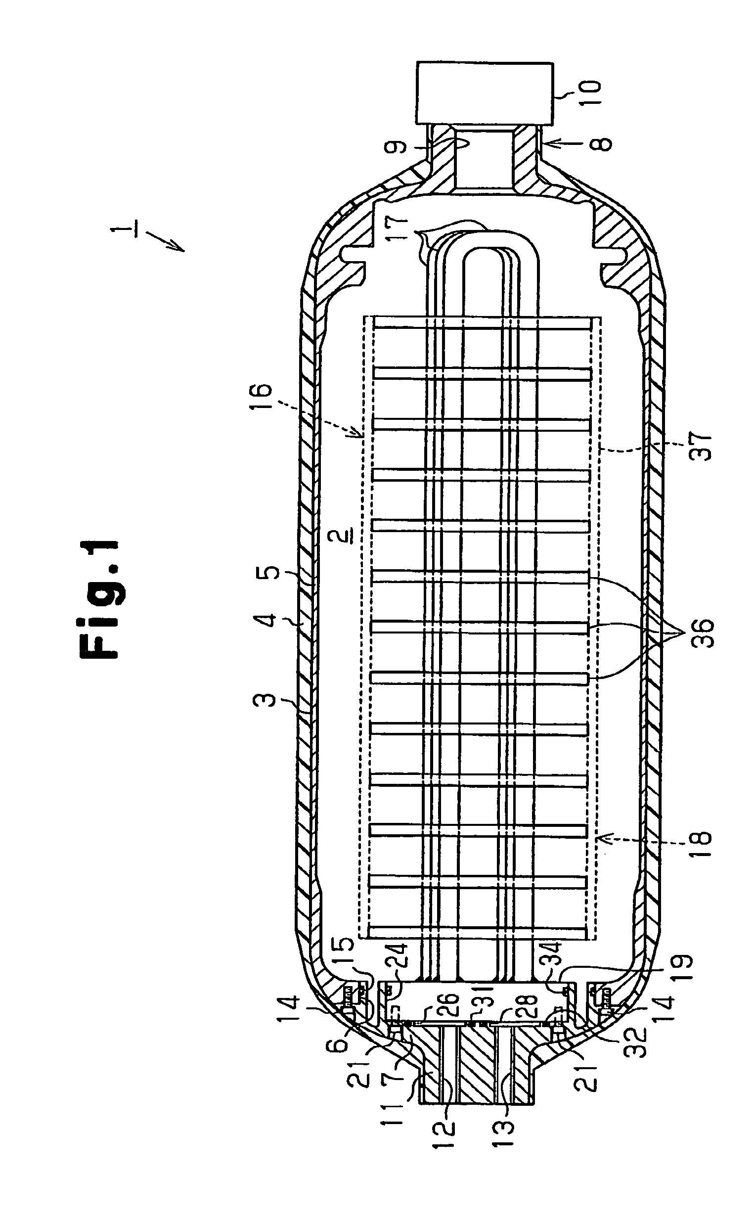
[0028]the present invention will now be described with reference to FIGS. 1 and 2.

[0029]The hydrogen storage tank 1 shown in FIG. 1 is an elongated cylindrical pressure tank. As viewed in FIG. 1, the right end of the tank 1 defines a distal end and the left end of the tank 1 defines a basal end. An accommodation chamber 2 is defined in the tank 1 to accommodate hydrogen gas in a high pressure state. The amount of hydrogen that may be accommodated in the accommodation chamber 2 is increased by increasing the pressure in the accommodation chamber 2. For example, when the pressure within the accommodation chamber 2 is set at 25 MPa, approximately 250 times the amount of hydrogen may be accommodated within the accommodation chamber 2 compared to when the interior pressure is set at atmospheric pressure.

[0030]The tank 1 includes a hollow liner 3, which is generally cylindrical, and a shell 4, which substantially covers the entire outer surface of the liner 3. The interior of the liner 3 ...

second embodiment

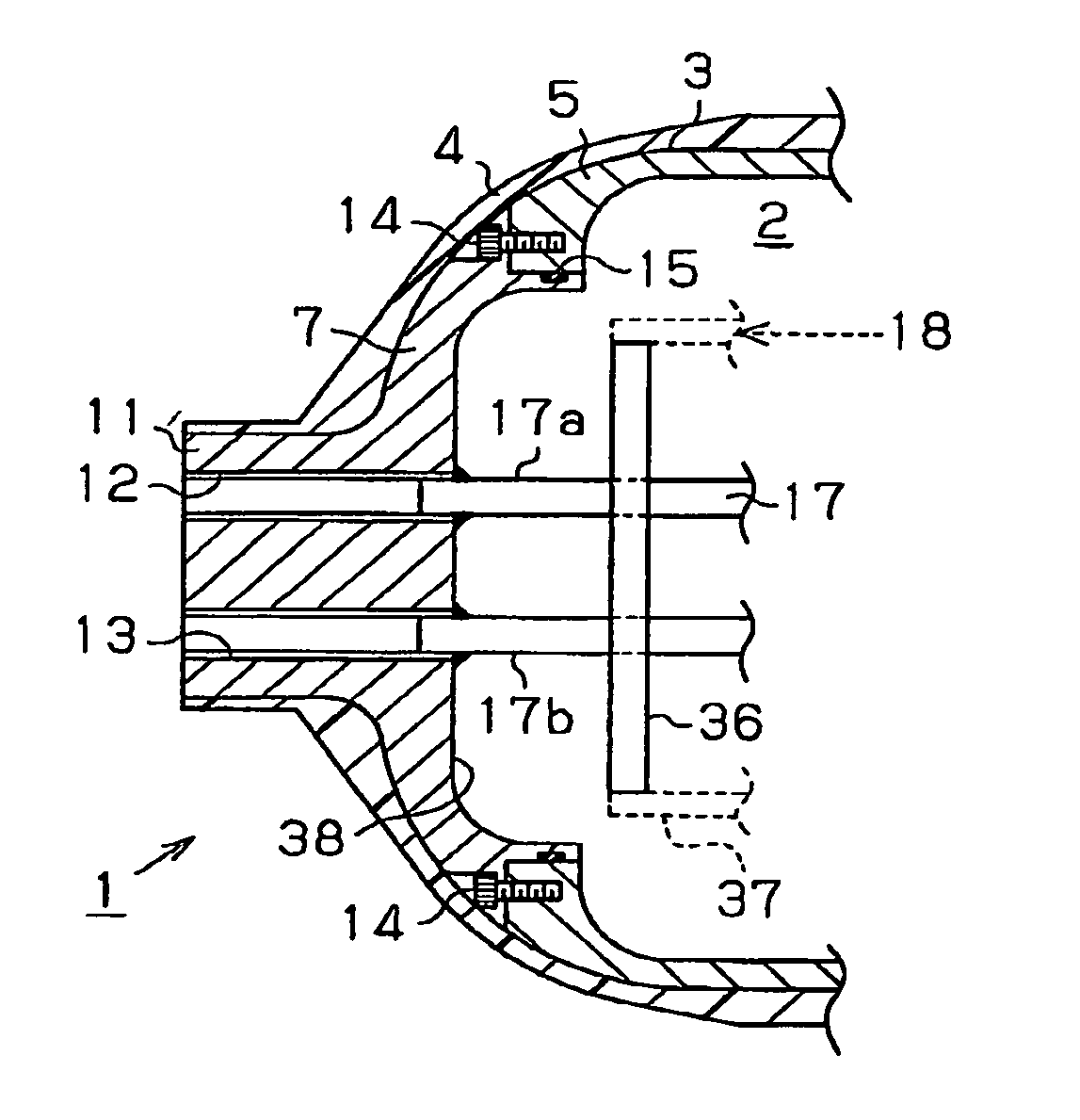
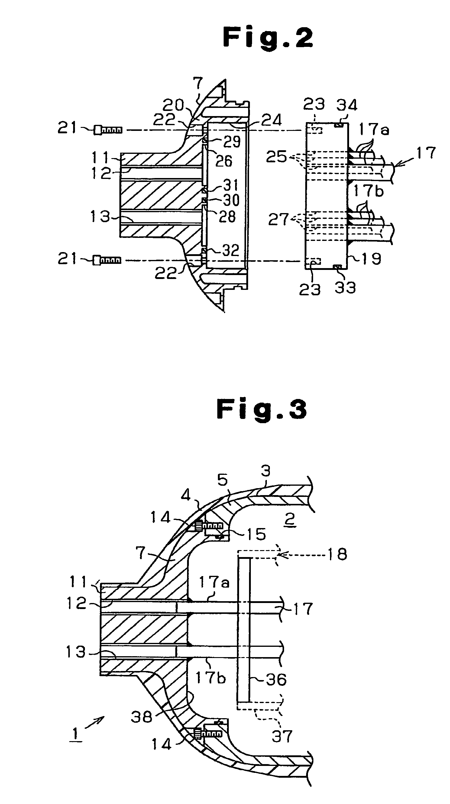
[0056]the present invention will now be described below with reference to FIG. 3.

[0057]The tank 1 of the second embodiment shown in FIG. 3 is identical to the tank 1 of the first embodiment shown in FIGS. 1 and 2 with the exception for one part. Among the components of the tank 1 shown in FIG. 3, the components differing from those of the tank 1 shown in FIGS. 1 and 2 are described below. Like or same reference numerals are given to those components that are the same as the corresponding components of the first embodiment. Such components will not be described in detail below.

[0058]In the tank 1 of FIG. 3, the heat exchanger 18 is connected directly to the cap 7 without using the header 19. The heat exchanger 18 has a single heat transfer tube 17. The upstream end 17a and the downstream end 17b of the heat transfer tube 17 are respectively aligned with through passages 12 and 13 and then fixed to the inner surface of the cap 7 through brazing or welding. A recess 38 is provided in t...

third embodiment

[0061]the present invention is described below with reference to FIGS. 4(a) and 4(b).

[0062]The third embodiment of the tank 1 shown in FIG. 4(a) has a structure similar to that of tank 1 of the first embodiment shown in FIGS. 1 and 2 with the exception that a part is omitted. Among the parts of the tank 1 shown in FIG. 4(a), parts which differ from the parts of the tank 1 shown in FIGS. 1 and 2 are described below, and parts which are identical or similar to those of the first embodiment are referenced by identical reference numbers and further description of these parts is omitted.

[0063]In the tank 1 shown in FIG. 4(a), the heat exchange unit 16 is connected to the main body 5 and not to the cap 7. The cap 7 covers an opening of the main body 5 at the distal end of the tank 1 and not the basal end of the tank 1. A gas passage 9, which connects the accommodation chamber 2 to the exterior, extends through the cap 7. A valve 10 is connected to the gas passage 9.

[0064]A mounting hole 4...


PUM

PropertyMeasurementUnit
atmospheric pressureaaaaaaaaaa
porosityaaaaaaaaaa
pressureaaaaaaaaaa

Abstract

A pressure tank includes a liner separated into a cap and a main body. A shell covers the outer surface of the liner. The shell is formed of a fiber reinforced plastic. A heat exchanger is arranged in the liner. A header is connected to the heat exchanger. The heat exchanger is supported on the liner by fastening the header to the cap or the main body.

Description

BACKGROUND OF THE INVENTION[0001]The present invention relates to a pressure tank;[0002]Recent years have seen the development of hydrogen engine automobiles and electric fuel cell automobiles to reduce the amount of carbon dioxide emitted from vehicles. In electric fuel cell automobiles, power is generated by electrochemical reaction of hydrogen and oxygen. The power is supplied to the motor to produce motive power. A pressure tank for the storage of hydrogen is generally installed in electric fuel cell vehicles. An example of such a pressure tank is disclosed in Japanese National Phase Laid-Open Patent Publication No. 2000-504810. The pressure tank disclosed in Japanese National Phase Laid-Open Patent Publication No. 2000-504810 is provided with a metal or resin liner and a shell. The shell covers the outer surface of the liner and functions to ensure pressure resistance of the pressure tank.[0003]In general, when gas is charged into a pressure tank, the temperature within the pre...

Claims


Application Information

Patent Timeline
Patent Type & Authority Patents(United States)
IPC IPC(8): F28F9/02F22B1/02F28D7/10
CPCF17C1/00F17C1/16F28D1/0213H01M8/04208F17C2201/0109F17C2201/035F17C2201/054F17C2201/056F17C2203/0604F17C2203/0619F17C2203/0621F17C2203/0636F17C2203/0639F17C2203/0643F17C2203/0646F17C2203/0648F17C2203/0658F17C2203/066F17C2203/0665F17C2203/067F17C2205/0305F17C2205/0323F17C2209/2154F17C2209/221F17C2209/228F17C2221/012F17C2221/014F17C2221/033F17C2223/0123F17C2223/035F17C2223/036F17C2227/0302F17C2227/0309F17C2227/0316F17C2227/0348F17C2227/0372F17C2260/011F17C2260/012F17C2260/018F17C2260/036F17C2265/066F17C2270/00F17C2270/0168F17C2270/0184F17C2270/0763Y02E60/321Y02E60/50Y02E60/32
Inventor TOH, KEIJIKUBO, HIDEHITOFUJITA, KATSUYOSHIKUMANO, AKIKOKIMBARA, MASAHIKOISOGAI, YOSHIHIROMORI, DAIGORO
Owner TOYOTA IND CORP
Why Eureka
Try Eureka