[0004]An object of the present invention consists of providing a rotary indexing table of the initially named kind which, in particular to the extent its drive unit is affected, can be realized with a comparatively low economic effort. The drive should preferably require such a low
power consumption that a cost-favorable
air cooling system is possible.
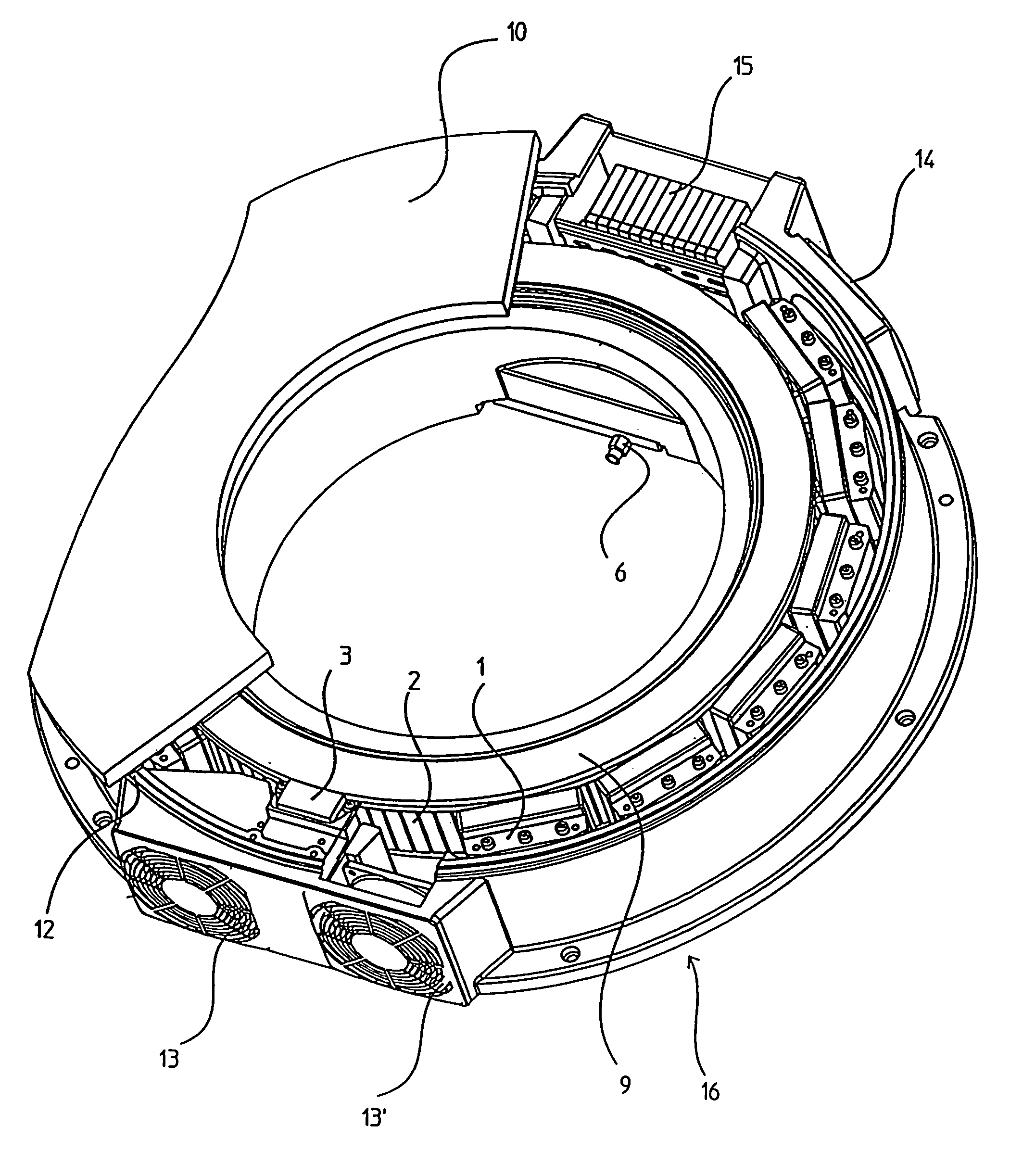
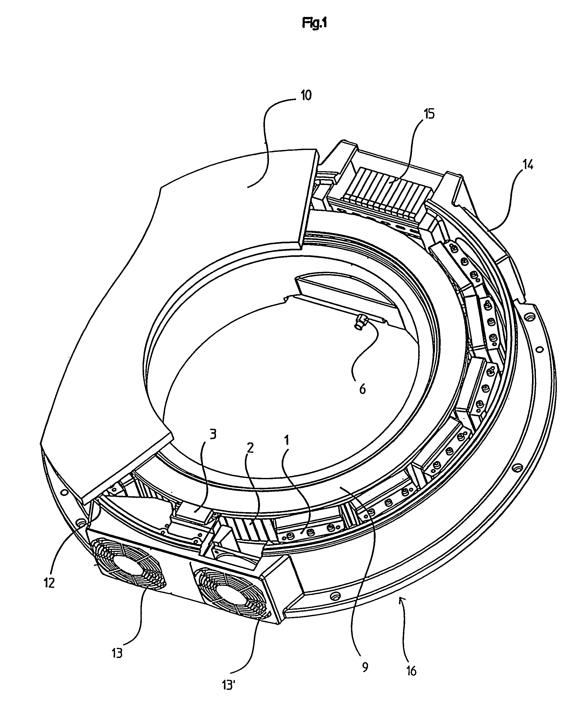
[0006]The object is achieved by a surprisingly easy measure, which was not, however, used in known rotary indexing tables to date. Instead of an individual, relatively powerful drive element, a plurality of individual drive elements are used which can be made correspondingly less powerful and which accordingly also cause a lower power consumption and, resulting from this, also a lower heat production. These advantages are also achieved in accordance with the invention in that the individual drive elements are not, for instance, arranged in the region of the axis of rotation of the plate, but rather in its circumferential region so that, on the operation of the rotary indexing table in accordance with the invention, comparatively low tangential forces produced in the region of the individual drive elements produce large torques. The individual drive elements can thereby be kept small, which then—as already mentioned—results in an advantageously low power consumption and an accordingly low heat development.
[0008]It is of
advantage for the individual drive elements to be arranged in equal distribution at least over part of the circumference of the plate, with them
lying substantially diametrically opposite one another in particular with respect to the axis of rotation. In such an arrangement, the radial forces produced by the individual drive elements are largely canceled out by the respectively oppositely disposed individual drive element without the bearing of the rotary indexing table being significantly strained.
[0009]The individual drive elements can, for example, be formed as electric motors each provided with a toothed wheel, with the toothed wheels engaging into a turntable connected to the plate. In this case, however,
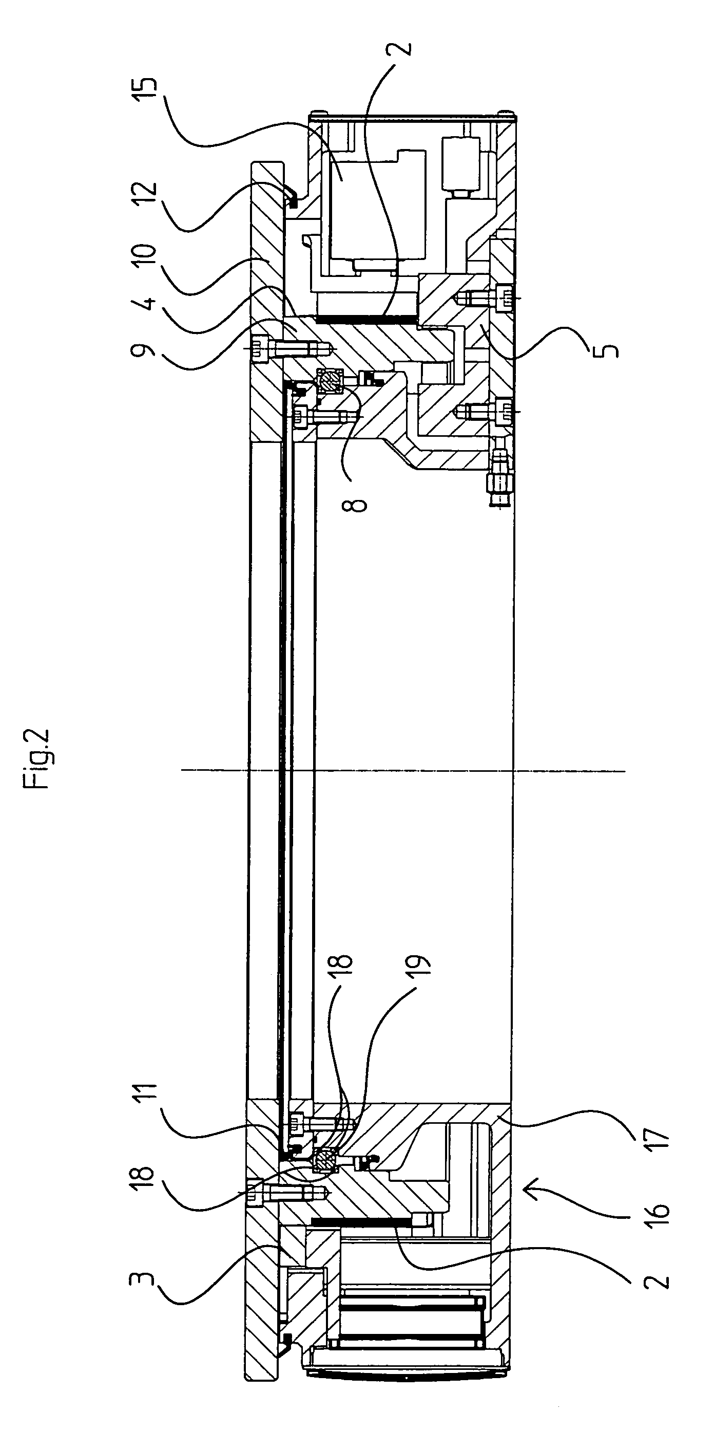
mechanical transmission elements are required, namely toothed wheels and a turntable, so that it is preferred for the plate to be provided along its total circumference with individual permanent magnets adjacent to one another which cooperate with electromagnets attached to the base unit, with these electromagnets
lying opposite the permanent magnets coupled to the plate. The latter embodiment of the individual drive elements can be realized in a particularly cost-favorable manner and furthermore has the
advantage that no mechanical connection has to be provided between the base unit and the plate—and accordingly also no
mechanical transmission element—in the region of the individual drive elements since the forces to be applied to the plate can be transmitted in a non-contact manner as electromagnetic forces. Such an
electromagnetic drive works largely wear-free in comparison with a
gear drive, whereby the service life of the individual drive elements can be substantially increased in an advantageous manner.
[0011]To determine the respective position of the plate relative to the base unit and to communicate corresponding information, for example, to a control computer, it is of
advantage for an
encoder to be provided for the determination of the relative position between the plate and the base unit. Such an
encoder can work, for example, with code markings attached to the plate and distributed over its circumference. These code markings can be made either the same as one another or different to one another, with it being advantageous with code markings the same as one another for at least one reference mark to be provided in the region of the code markings so that not only relative movements between the plate and the base unit can be determined, but also an absolute angular position of the plate can be determined. To detect the code markings or reference marks, the base unit is provided with an optical, magnetic or
inductive sensor.
[0013]The plate and the base unit can each be made in ring shape, with the central openings of the plate and of the base unit being substantially aligned with one another. This makes it possible for workpieces arranged on the plate to be worked not only starting from the circumferential region of the plate, but also starting from the openings, since working apparatuses can be provided both in the circumferential region of the plate and in the region of the openings.

