Supercharge Your Innovation With Domain-Expert AI Agents!

DNL/INL trim techniques for comparator based analog to digital converters

a technology of analog to digital converter and comparator, applied in the field of electronic devices, can solve the problems of generating differential nonlinearity (dnl) and integral nonlinearity (inl) distortions in the system, the inability to manufacture the resistors of the voltage divider to exact values, and the inability of comparators to have imperfections

Active Publication Date: 2006-12-26
MICROELECTRONICS TECH INC
View PDF15 Cites 13 Cited by
  • Summary
  • Abstract
  • Description
  • Claims
  • Application Information

AI Technical Summary

Benefits of technology

This approach reduces DNL and INL errors by allowing precise adjustment of comparator thresholds, achieving high-resolution conversions with reduced size and power consumption, making it suitable for larger resolution ADCs.

Problems solved by technology

Due to process variables, the multiple resistors of the voltage divider cannot be fabricated to exact values.
In addition, the comparators typically also have imperfections, such as imprecise current sources and base currents that affect the resistive ladder.
These inaccuracies cause the comparators to change states at the wrong times, generating differential nonlinearity (DNL) and integral nonlinearity (INL) distortions in the system.
In either case, any errors introduced by the flash ADC will propagate through the entire conversion process, creating distortions in the digital output.
For a high precision ADC, these errors cannot be tolerated.
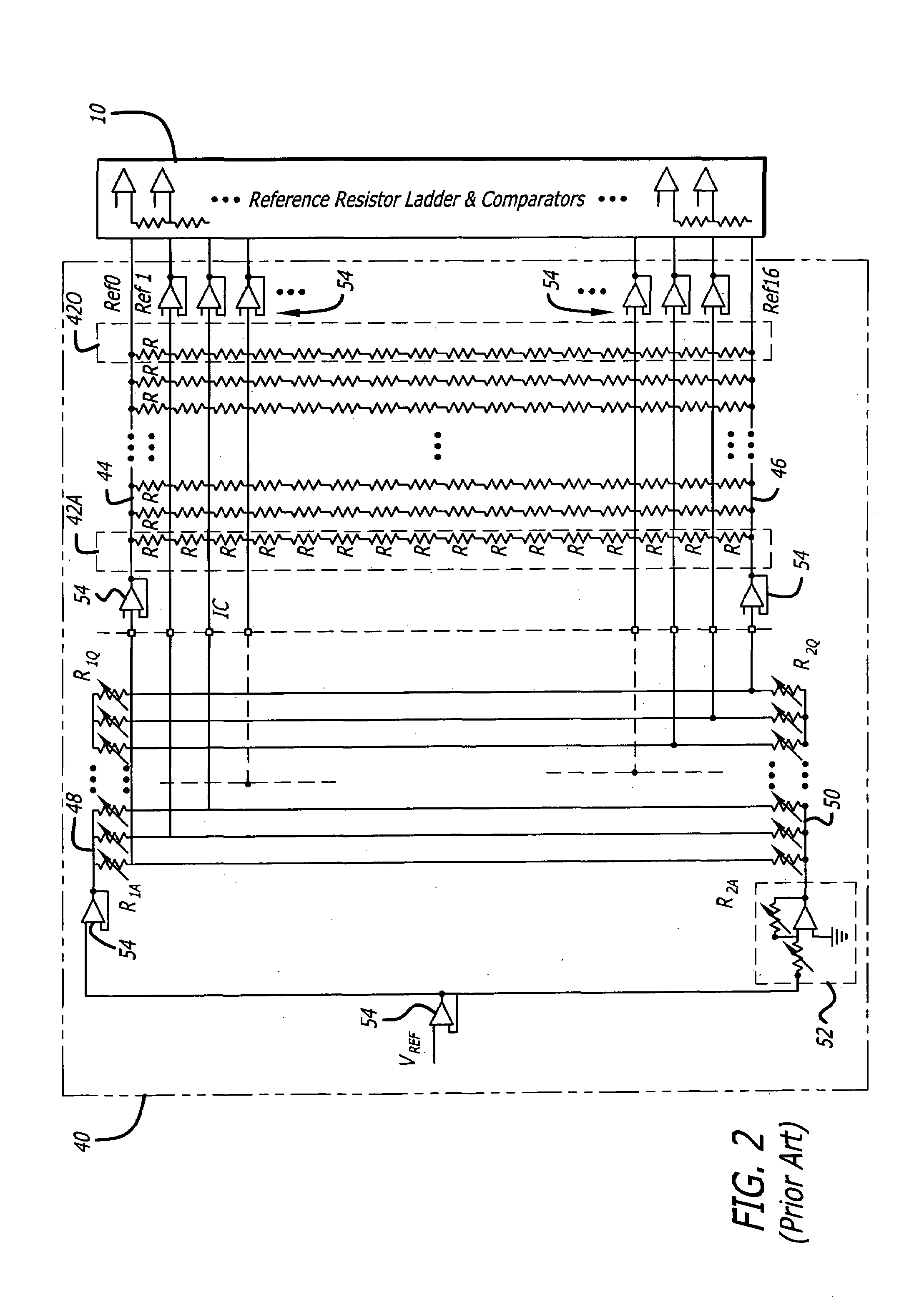
The resistive ladder by itself cannot be trimmed to correct any individual threshold because trimming one threshold will affect all the other thresholds.
This approach utilizes significant surface die area and high power consumption.
While this solution achieves the desired accuracies for low resolution (up to about 4–5 bit) ADCs, it is impractically large for larger resolution ADCs.
There is no equivalent approach in the prior art for zeroing errors in a differentially driven comparator bank.

Method used


Image

  • DNL/INL trim techniques for comparator based analog to digital converters
  • DNL/INL trim techniques for comparator based analog to digital converters
  • DNL/INL trim techniques for comparator based analog to digital converters

Examples


Embodiment Construction

[0018]Illustrative embodiments and exemplary applications will now be described with reference to the accompanying drawings to disclose the advantageous teachings of the present invention.

[0019]While the present invention is described herein with reference to illustrative embodiments for particular applications, it should be understood that the invention is not limited thereto. Those having ordinary skill in the art and access to the teachings provided herein will recognize additional modifications, applications, and embodiments within the scope thereof and additional fields in which the present invention would be of significant utility.

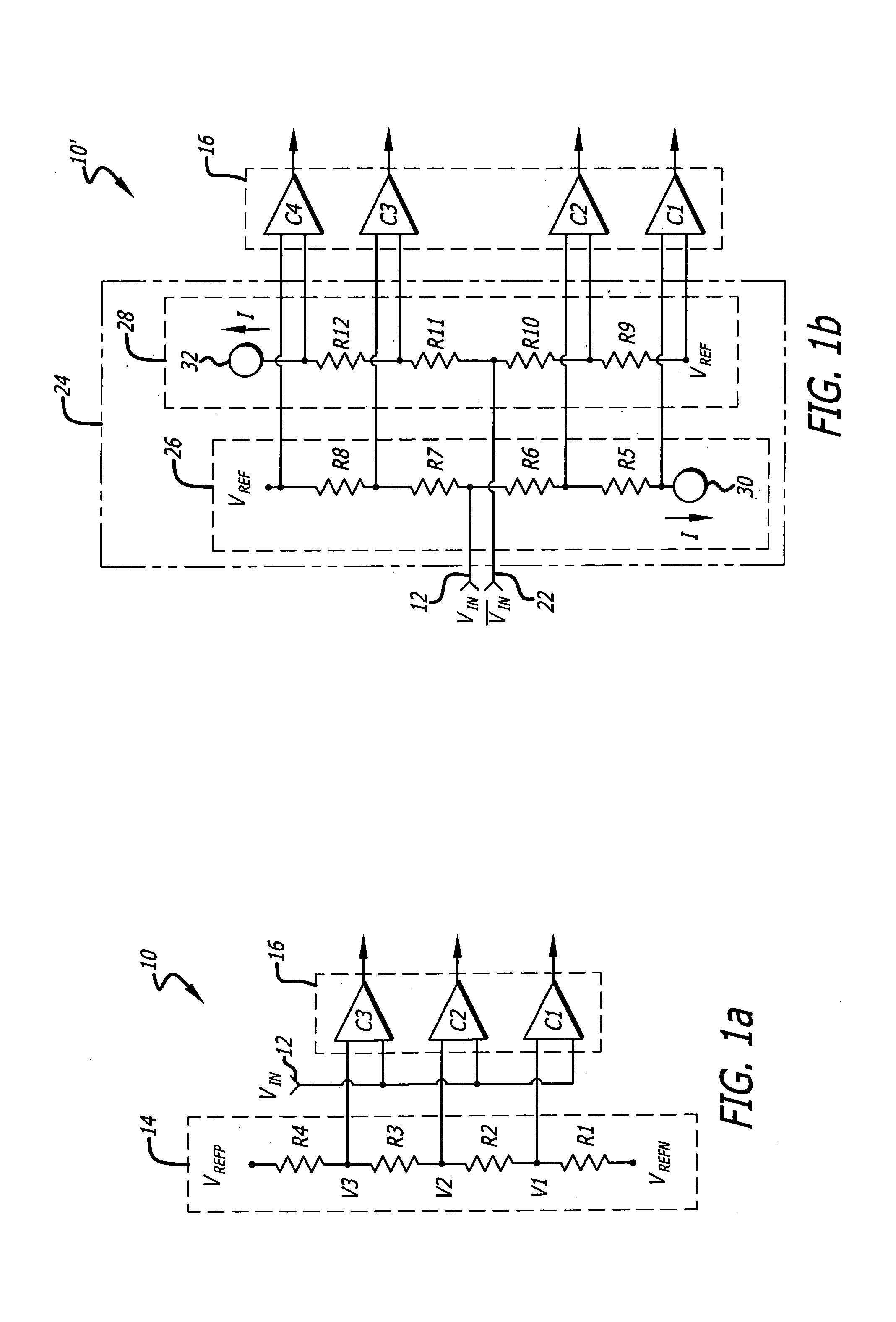
[0020]FIG. 1a is a simplified schematic of an illustrative single-ended flash ADC 10. The ADC 10 includes an input terminal 12, a resistive ladder 14, and a comparator bank 16 comprised of a plurality of comparators C1, C2, and C3. For simplicity, a two-bit ADC 10 having only three comparators C1, C2, and C3 is shown in FIG. 1a. The teachings of the ...


PUM


Abstract

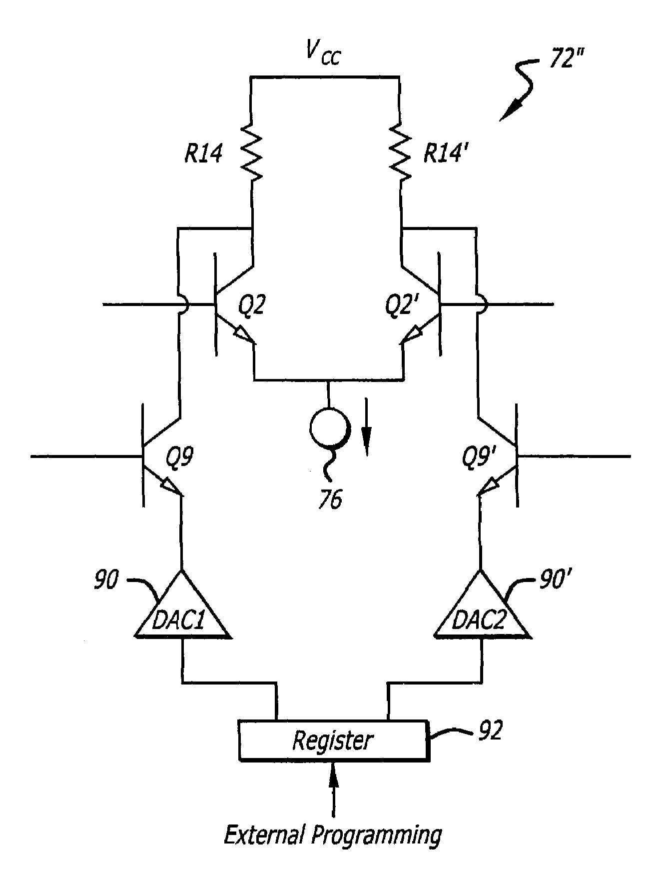
A trimmable comparator. The novel comparator includes a first circuit for comparing first and second input signals and in accordance therewith generating first and second output signals, and a second circuit for adding an adjustable current to the first output signal such that the comparator is in a transition state when the first and / or second input signals are at desired levels. The comparator may also include a third circuit for adding an adjustable current to the second output signal. In the illustrative embodiments, the second and third circuits are implemented using adjustable current sources with trimmable resistors, or using digital to analog converters. The novel comparators may be used in an analog to digital converter to allow the converter thresholds to be adjusted to desired levels.

Description

CROSS-REFERENCE TO RELATED APPLICATIONS[0001]This application claims the benefit of U.S. Provisional Application No. 60 / 529,334, filed Dec. 12, 2003, the disclosure of which is hereby incorporated by reference.BACKGROUND OF THE INVENTION[0002]1. Field of the Invention[0003]The present invention relates to electronics. More specifically, the present invention relates to comparators and analog to digital converters.[0004]2. Description of the Related Art[0005]Analog to digital converters are widely used for converting analog signals to corresponding digital signals for many electronic circuits. For example, a high resolution, high speed analog to digital converter (ADC) may find application in broadband communications, video circuits, radar, and electronic warfare applications.[0006]The fastest ADC architecture is called “flash” conversion. A flash ADC produces an N-bit digital output in one step using a comparator bank comprised of 2N−1 parallel comparators. Each comparator compares ...

Claims


Application Information

Patent Timeline
Patent Type & Authority Patents(United States)
IPC IPC(8): H03M1/06H03K5/24H03M1/10H03M1/36
CPCH03K5/2418H03M1/1057H03M1/1061H03M1/363
Inventor DEVENDORF, DON C.HIRATA, ERICK M.LINDER, LLOYD F.
Owner MICROELECTRONICS TECH INC
Features
  • R&D
  • Intellectual Property
  • Life Sciences
  • Materials
  • Tech Scout
  • Unparalleled Data Quality
  • Higher Quality Content
  • 60% Fewer Hallucinations
Learn More