

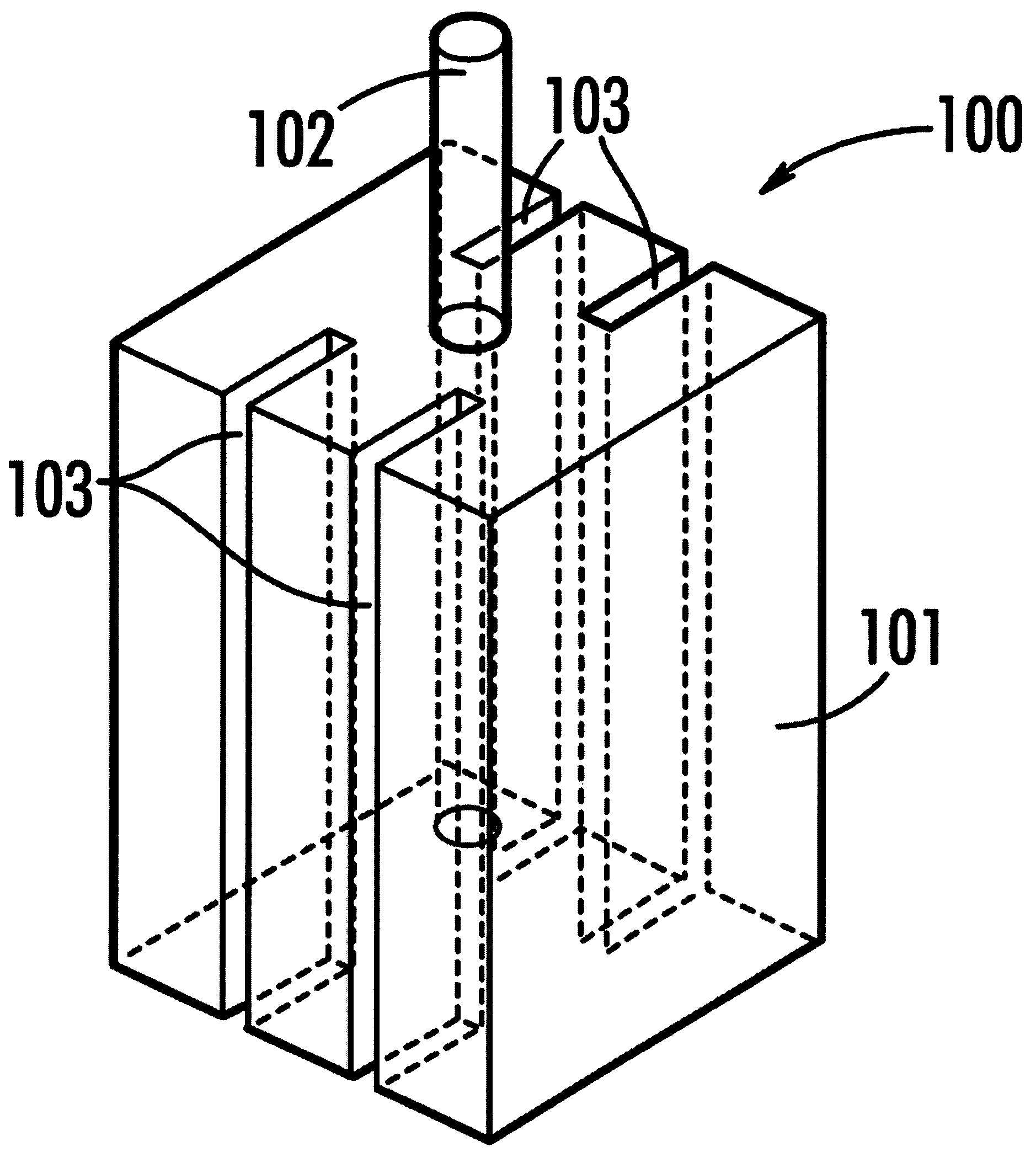
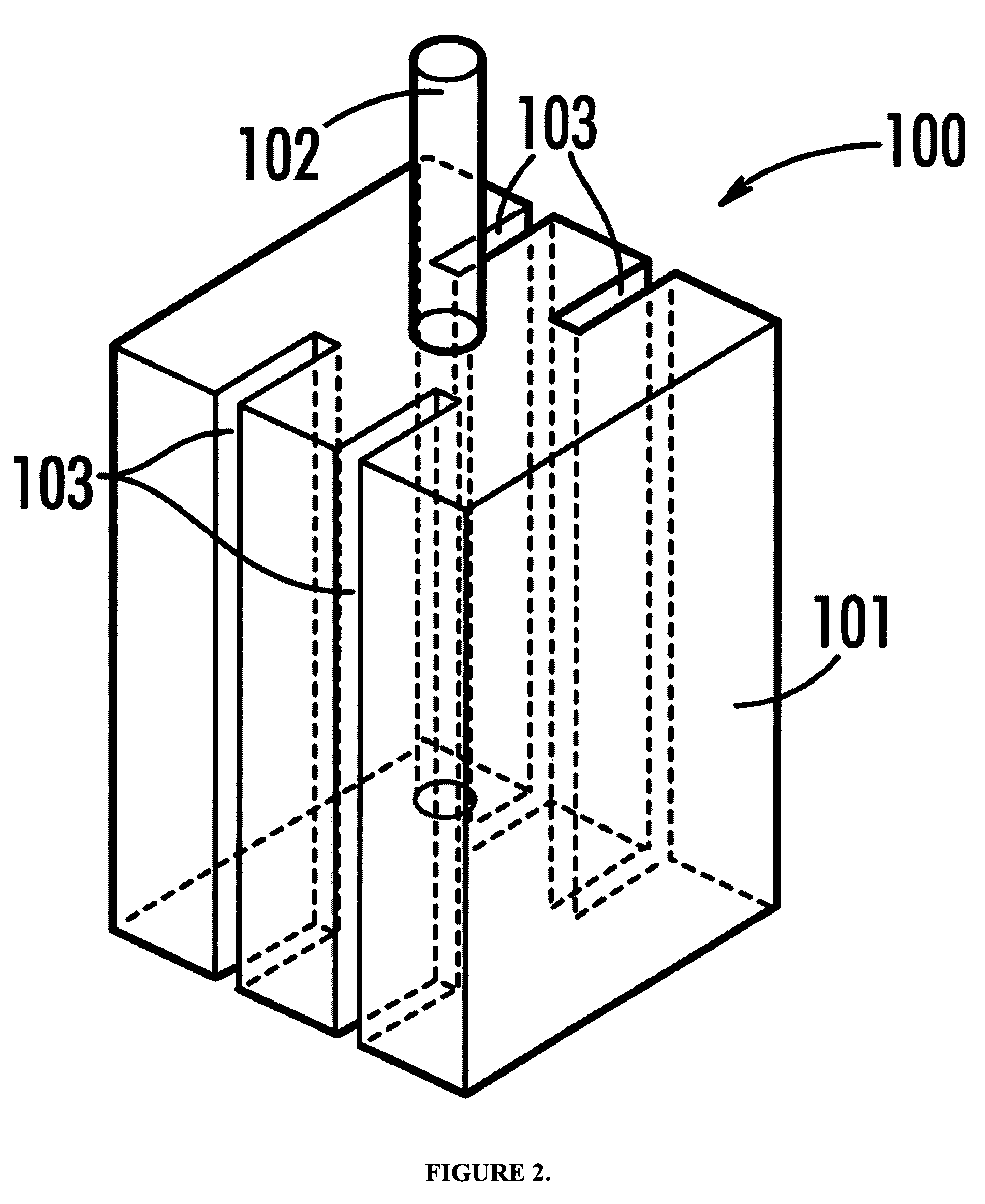
Fluted anode with improved capacitance and capacitor comprising same
a fluted anode and capacitance technology, applied in the direction of capacitor electrodes, electrolytic capacitors, liquid electrolytic capacitors, etc., can solve the problems of loss of capacitance in the finished device, difficult coating of internal dielectric surfaces with solid cathodes, and pore diameter decrease, so as to improve the capacitance recovery of finished capacitors, improve the uniformity of cathode coating, and improve the effect of capacitance recovery
- Summary
- Abstract
- Description
- Claims
- Application Information
AI Technical Summary
Benefits of technology
Problems solved by technology
Method used
Image

Examples
example 1
[0043]Two sets of anodes were pressed using 62,000 CV / g powder. The anode dimensions were 3.25×3.25×4.83 mm. The density of the anodes after pressing was 6.0 g / cc. The first set of comparative anodes employed a conventional anode with no flutes. The inventive group was pressed with four flutes of dimensions 0.20 mm wide by about 1.0 mm deep. The anodes were vacuum sintered to form porous anodes suitable for manufacturing solid electrolytic capacitors. After an anodization step to form the dielectric, both groups of anodes were processed through a series of 13 manganese nitrate dip / conversion cycles together. The anodes were then fractured to reveal the manganese dioxide distribution. Pictures were taken with an optical microscope to demonstrate the differences in manganese dioxide distribution between these two anode designs. FIG. 3 is a photomicrograph of the MnO2 distribution in the conventional anode. Outside the rectangular box the comparative anodes exhibit a shading which is c...
example 2
[0047]Anodes were pressed using 62,000 CV / g powder. The anode dimensions were 3.25×3.25×4.83 mm. The density of the anodes after pressing was 6.0 g / cc. The first set of anodes employed a conventional anode (no flutes). In order to demonstrate the effect of flute width and depth on the electrical characteristics of a solid electrolytic capacitor several additional groups were pressed. These groups were pressed using 62,000 CV / g powder and external anode dimensions of 3.25×3.25×4.83 mm. The density of the anodes after pressing was 6.0 g / cc. Flute width was varied between 0.2 mm and 0.66 mm. Flute depth was varied between 0.51 mm and 1.27 mm. After sintering, the anodes were anodized to 38 volts to form the dielectric. The Ta volume was calculated based on the external dimensions of the anode (0.3.25×3.25×4.83 mm) minus the dimensions of the flutes (e.g. 4×0.56×1.0 mm). Wet capacitance was calculated from the Ta volume, press density, powder charge, and formation voltage as indicated i...
PUM
| Property | Measurement | Unit |
|---|---|---|
| Length | aaaaa | aaaaa |
| Length | aaaaa | aaaaa |
| Length | aaaaa | aaaaa |
Abstract
Description
Claims
Application Information